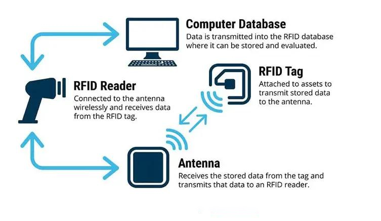
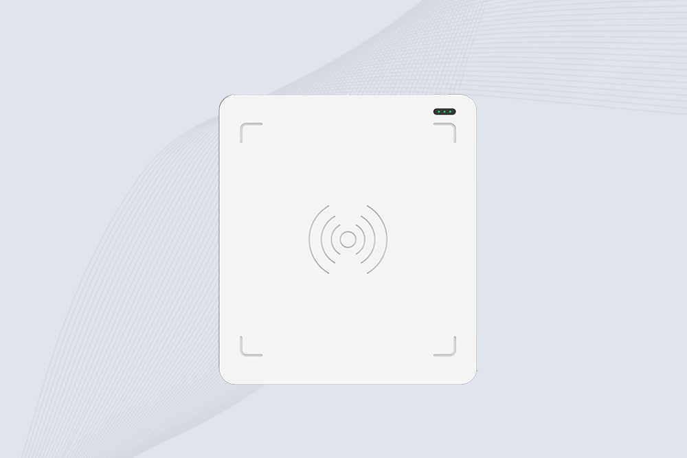
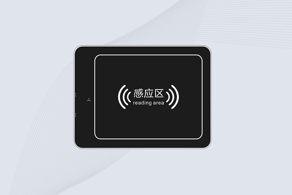
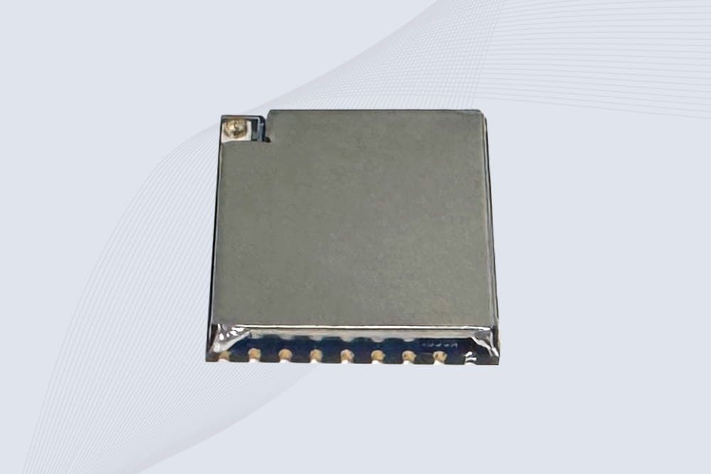
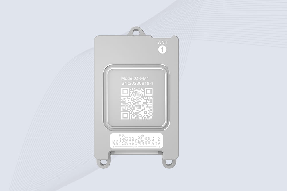
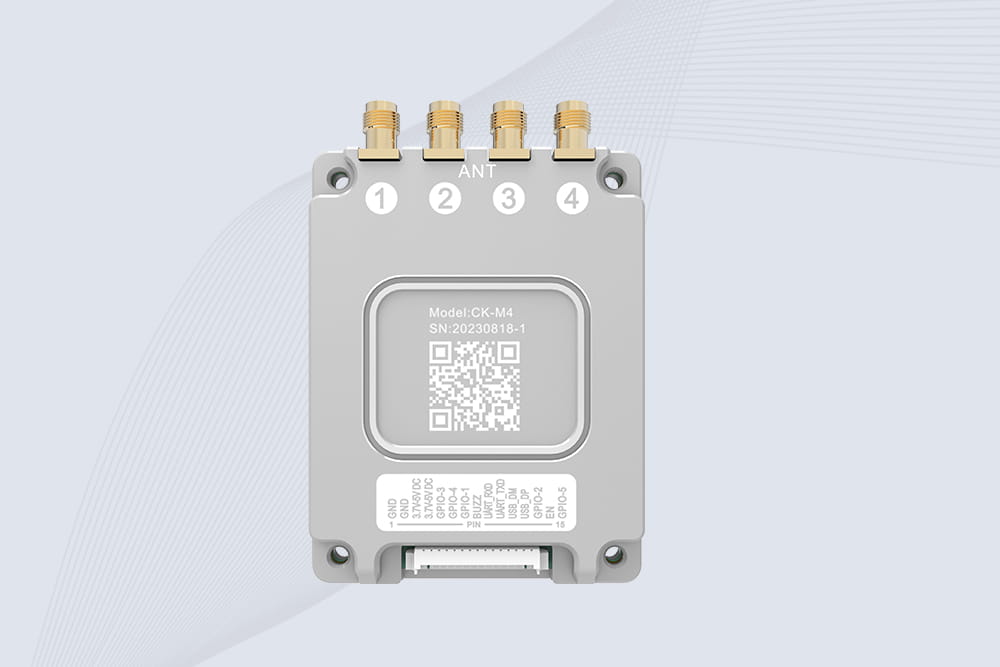
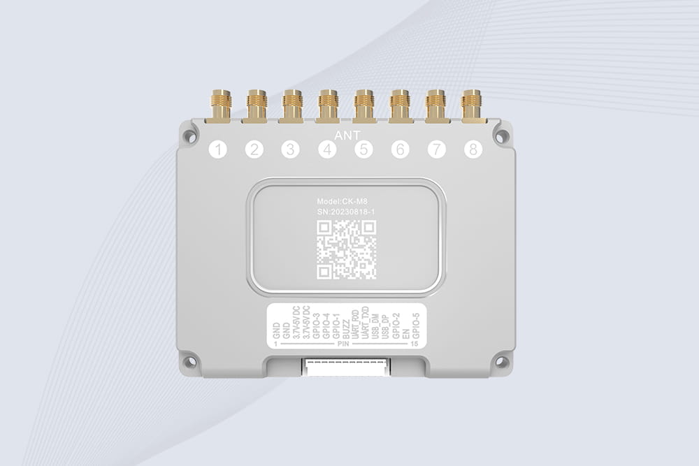
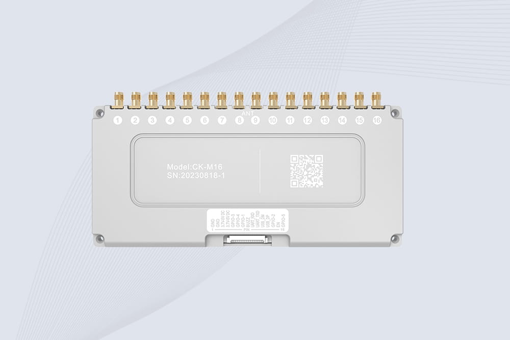
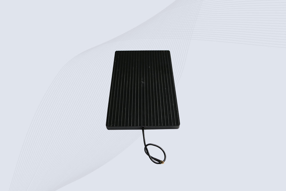
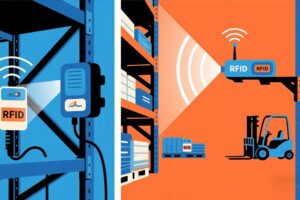
A how rfid works diagram shows how an RFID tag, reader, antenna, and software interact to identify tagged objects and process their data. The reader communicates with compatible tags using radio waves, then passes captured information to an application for inventory, tracking, access control, or other operational tasks.
An RFID system can look simple on paper: a tag, an antenna, a reader, and a computer. In an actual warehouse, however, the result depends on details that a basic diagram may leave out. A carton might pass through a reading zone at an angle, several tags may respond together, or a metal surface may change how the radio signal behaves.
A useful diagram therefore needs to show more than the equipment. It should explain the direction of communication, where tag data is captured, how the software receives it, and what business event follows the read.
For businesses evaluating RFID for the first time, that distinction matters. Reading a tag is not the same as tracking an item accurately. The diagram should connect the radio-frequency process to the operational process it is intended to support.
What Does a how rfid works diagram Show?
A how rfid works diagram illustrates the relationship between the physical RFID hardware and the software that uses the captured information. It normally includes four main elements:
RFID tag: Attached to an item, package, asset, or access credential.
RFID reader: Sends interrogation signals and receives tag responses.
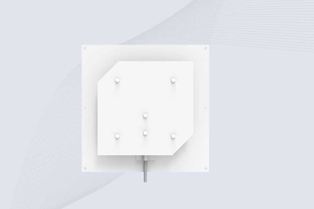
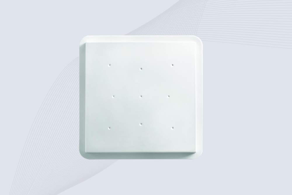
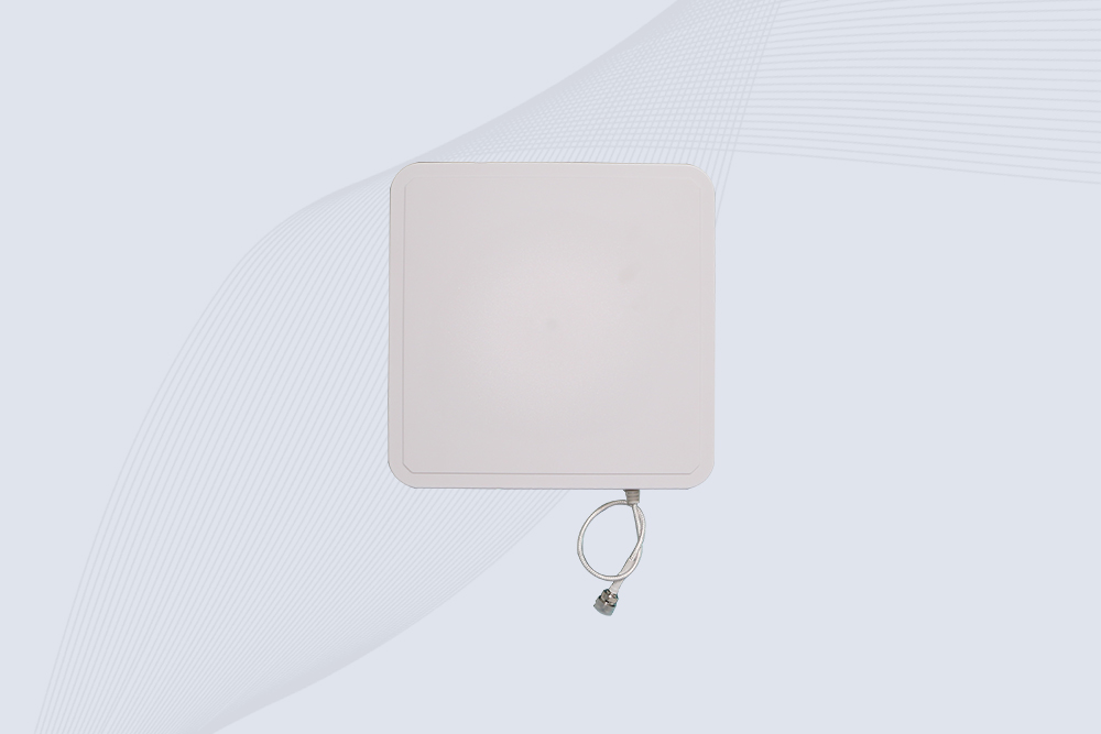
RFID antenna: Transmits and receives radio-frequency energy; it may be built into the reader or connected externally.
Software or host system: Processes tag identifiers and connects read events to inventory, asset, access, or other business records.
Some installations also include network equipment, photoelectric sensors, programmable logic controllers (PLCs), weighing systems, or conveyor controls. These components are not required for every RFID system. They appear when the application needs to associate a tag read with a specific time, location, direction, or physical event.
The diagram below represents a typical passive UHF RFID arrangement. Exact hardware connections vary by product, and an integrated reader may combine the reader electronics and antenna in a single enclosure.
An RFID system links wireless tag identification with reader hardware and business software.
The four components and their roles
Component
What it does
What the diagram should make clear
RFID tag
Stores an identifier and, depending on the tag, additional data
The tag is attached to or associated with the object being identified
Antenna
Sends and receives RF energy
Its position and coverage help define the reading zone
Reader
Communicates with tags and processes their responses
The reader controls the interrogation process and collects tag data
Host software
Uses the read data in an application
A tag read must be interpreted against business records and workflow rules
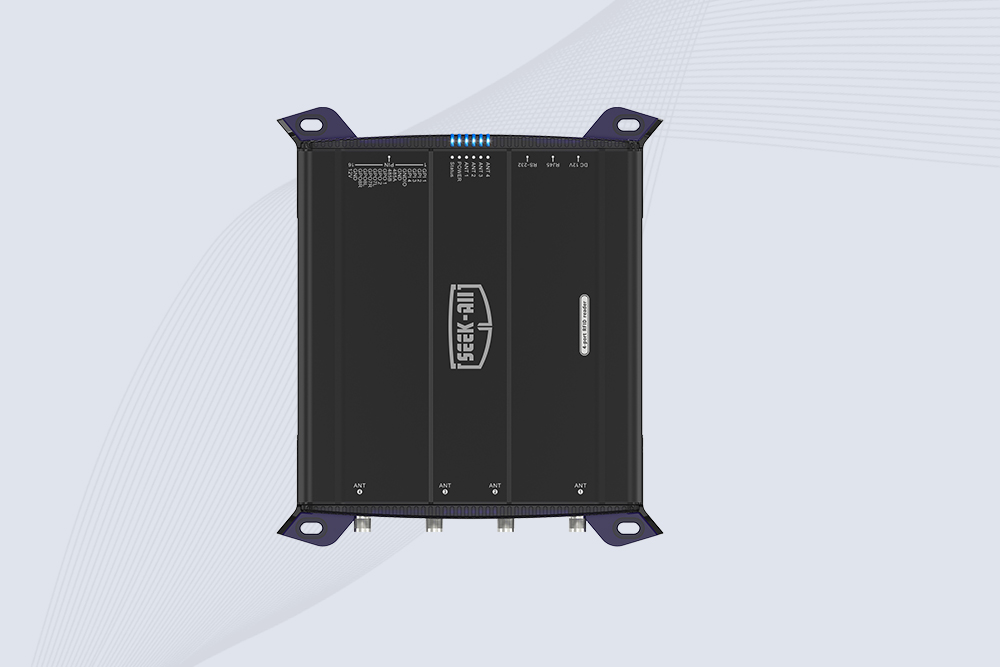
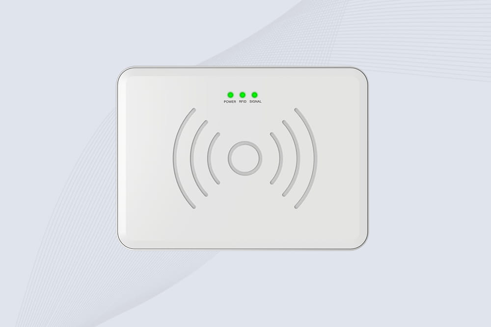
One important technical detail: the antenna and reader are not always separate devices. A fixed RFID reader may connect to one or more external antennas, while an integrated UHF reader can contain both the reader electronics and antenna. A handheld reader may also combine the reader, antenna, controls, and display in one unit.
The best diagram reflects the hardware being considered, rather than presenting one configuration as universal.
How RFID Communication Works: Follow the Signal
The most useful way to read an RFID diagram is to follow the process from the reader to the tag, and then from the reader to the software. In a typical passive UHF installation, the sequence works as follows.
1. The reader initiates communication
The reader activates its RF circuitry and sends a signal through its antenna. In a passive RFID system, this signal provides the energy that enables a compatible tag to respond.
The precise operating frequency depends on the RFID system and the region in which it is deployed. Passive UHF RFID is commonly used for supply-chain and inventory applications, but the configured band must comply with local regulations. A reader intended for one region should not automatically be assumed to support every other region’s frequency requirements.
2. The tag responds to the reader
When a compatible passive tag receives sufficient RF energy, its chip and antenna enable it to respond according to the protocol supported by the system. The response can include a tag identifier and other permitted information.
The tag does not usually send its information in the same way that a phone sends data over Wi-Fi. Passive UHF systems commonly use backscatter: the tag changes how it reflects the reader’s radio signal, allowing the reader to decode the response.
This distinction is worth showing in a technical diagram. The reader supplies the interrogation signal, while the passive tag responds by modulating the reflected signal. The tag does not normally need its own battery to perform this operation.
3. The reader captures tag data
The reader decodes the tag response and makes the captured data available to the host system. Depending on the protocol, reader, and application, it may identify multiple tags within its reading zone.
However, a diagram should not imply that every tag in a room will always be read. Successful reads depend on factors such as tag design, antenna placement, tag orientation, RF power, interference, materials near the tag, and the movement of objects through the field.
A carton entering a portal, for example, may contain multiple tagged items. The system must be designed so the intended tags can be read reliably without collecting too many unrelated tags from adjacent shelves or work areas.
4. The software interprets the data
The reader’s output is not automatically a complete inventory record. The application must determine what the identifier represents and how to use it.
A software platform might match the tag identifier to an item record, update a stock count, record a checkpoint event, or verify an access credential. Depending on the implementation, the reader communicates with the host through Ethernet, serial communication, USB, a middleware service, or another supported interface.
A strong diagram shows this boundary clearly: the reader captures RFID data; the application turns that data into a business action.
5. The system records an event
The last stage is where the design becomes operationally useful. A tag read can be associated with an event such as receiving, dispatch, return, movement through a checkpoint, or entry into a controlled area.
The system may need to apply business rules before updating a record. For example, repeated reads of the same tag over a short interval may need to be filtered, while reads at two separate checkpoints may represent two distinct movements.
This is why RFID tracking diagrams should include the application or event-processing layer rather than ending at the reader.
RFID Works Diagram: Passive, Active, and Different Frequencies
Not every RFID diagram represents the same type of system. Passive UHF RFID, HF/NFC, and active RFID use different communication arrangements, so the diagram should identify the technology before showing its operating sequence.
RFID type
Typical frequency or technology
How communication works
Common applications
LF RFID
Commonly 125–134 kHz
Short-range inductive coupling
Animal identification and specialized access systems
HF RFID
Commonly 13.56 MHz
Near-field inductive communication
Cards, tickets, document identification, and NFC applications
Passive UHF / RAIN RFID
Regional bands within approximately 860–930 MHz
Reader energizes the tag; the tag responds through backscatter
Warehouse inventory, logistics, retail, and asset tracking
Active RFID
Frequency varies by system
Battery-powered tag transmits a signal
Selected tracking and real-time location applications
GS1 describes passive UHF RFID as a technology used for fast asset identification, inventory, and tracking. Depending on the environment, its reading range can reach around 10 meters. That is a capability reference, not a guarantee for every tag or installation.
The practical lesson for anyone preparing a how rfid works diagram is straightforward: label the RFID type and show its actual communication method. A diagram that depicts a passive label transmitting continuously like a battery-powered beacon can give equipment buyers the wrong idea about how the system operates.
Why frequency matters in a real installation
Frequency affects how RFID interacts with the surrounding environment, but frequency alone does not determine performance.
For example, a UHF portal can be suitable for identifying tagged cartons as they move through a warehouse checkpoint. A short-range HF reader may be more appropriate for a user presenting a card at a controlled access point. The correct choice depends on the required reading distance, tag format, materials, throughput, and operating conditions.
Before choosing equipment, answer three questions:
What is being identified? A book, garment, pallet, reusable container, access card, or industrial asset may require a different tag design.
Where does identification occur? A desktop station, conveyor, doorway, shelf, or open warehouse area creates a different reading zone.
What should happen after a successful read? The software might update inventory, validate an item, record movement, or trigger an alert.
These questions help determine which blocks belong in the diagram and which specifications actually matter.
A Real-World RFID Diagram: From Warehouse Checkpoint to Inventory Record
Consider a distribution center receiving cartons from a supplier. Each carton carries a compatible RFID tag, and a fixed UHF reader is installed near the receiving lane.
As cartons pass through the checkpoint, the reader captures available tag identifiers. The warehouse application compares those identifiers with expected shipment records. If the receiving process is configured correctly, the software can flag missing items, unexpected tags, or duplicate events for review.
The key is the relationship between the read zone and the business event. A tag detected near a receiving door does not automatically prove that the carton entered the building. It might be on a nearby pallet, inside an adjacent staging area, or moving in the opposite direction. Reader placement, antenna configuration, event logic, and sometimes an additional sensor help establish what the read actually means.
A defined RFID reading zone helps associate tag reads with receiving and inventory workflows.
What the diagram does not tell you automatically
A static diagram can explain the architecture, but it cannot prove that the installation will perform as expected. A commissioning test should examine the real environment, especially when several tags are moving together.
Pay attention to these details:
Read-zone boundaries: Can the reader capture the intended tags without collecting unrelated tags nearby?
Tag orientation: Does the tag remain readable when cartons or products rotate?
Packaging and materials: Are tags mounted near metal, liquids, foil, or other materials that may affect RF performance?
Movement speed: Can the system read tags reliably at the actual conveyor or vehicle speed?
Repeated reads: Does the software distinguish a new movement event from repeated detections of the same tag?
Application response: Does a successful read update the correct item record, or does it merely appear in a reader log?
These checks are often more useful than comparing maximum-distance figures alone. GS1 notes that passive UHF read range varies with the environment and equipment, and that the shape of the readable area can be as important as distance.
What real inventory research tells us
An RFID diagram explains the technology; field research helps explain why businesses implement it.
In a study published in Production and Operations Management, researchers Bill C. Hardgrave, John A. Aloysius, and Sandeep Goyal examined RFID-enabled inventory visibility in two retail field experiments. The first experiment covered one product category in 13 stores over 23 weeks. The researchers reported an approximately 26% reduction in inventory record inaccuracy associated with RFID-enabled visibility. Results in the second experiment varied by product category.
That figure should not be treated as a guaranteed result for every RFID deployment. It does, however, illustrate an important point: the business benefit comes from connecting reliable tag reads to inventory processes, not from installing a reader in isolation.
For Cykeo’s technical content, the diagram should therefore make two separate data paths visible:
The RF path between reader antenna and tag.
The information path between reader, application, and inventory records.
Keeping those paths distinct makes the explanation more accurate for engineers, system integrators, and operations teams.
How to Draw a Clear RFID System Flowchart
A useful RFID flowchart should explain both the technical process and the business outcome. It should help a reader understand what happens when a tag enters the reading zone, how the reader passes data to the application, and what the application does with that information.
For a Cykeo product page or technical FAQ, avoid drawing every component as if it were mandatory. Start with the core system, then add sensors, network equipment, or other devices only when the application requires them.
A practical RFID workflow
1. RFID tag enters the reading zone
A compatible tag is attached to an item, carton, asset, or credential.
2. Reader and antenna communicate with the tag
The reader interrogates the tag and receives its response.
3. Tag data reaches the host application
The reader sends captured data through a supported interface or network connection.
4. Software validates and processes the event
The application matches the identifier to a record and applies its business rules.
5. The business record is updated
Examples include receiving confirmation, inventory adjustment, or an access decision.
This flowchart is a conceptual model. Actual reader interfaces, middleware, sensors, and software logic vary by implementation.
Why the software stage deserves its own box
One common diagram mistake is connecting the RFID reader directly to an “inventory updated” symbol without showing the processing in between.
Suppose a reader detects the same carton tag six times as the carton moves through a portal. The application may need to treat those detections as one receiving event, not six separate arrivals. Alternatively, the same tag detected at a dispatch checkpoint several hours later may represent a genuinely new event.
The application therefore needs rules for duplicate filtering, event timing, location, and item status. Some filtering may also occur inside the reader or middleware, but the diagram should make clear where the final business decision is made.
A technically accurate diagram separates these stages:
RFID identification: The reader captures tag data.
Data handling: The reader, middleware, or application filters and transports the data.
Business processing: The software determines what the read means.
Record update: The relevant system stores the resulting event.
This layout is especially helpful when the diagram will be used by both purchasing teams and software integrators. Buyers can see the complete solution, while engineers can identify where interfaces and business rules need to be configured.
Which RFID Diagram Should You Use for Your Application?
The right diagram depends on where the tag is read and what the system must do afterward. A desktop RFID reader, fixed industrial reader, and warehouse portal may use related technology, but their operating arrangements are different.
Diagram type
Main components to show
Best suited to
Desktop RFID reader diagram
Tag or card, desktop reader, USB or supported host connection, software
Tag registration, card encoding, controlled item handling
Fixed UHF RFID reader diagram
Fixed reader, antenna or integrated antenna, network connection, application
Inventory checkpoints, access points, production lines
Reader, antenna placement, conveyor, optional photoelectric sensor, control software
Item identification on a production or sorting line
RFID access-control diagram
Credential, reader, access controller or application, door hardware
Authorized entry and exit
RFID asset-tracking diagram
Tags, fixed or handheld readers, asset database, event or location records
Asset identification and movement history
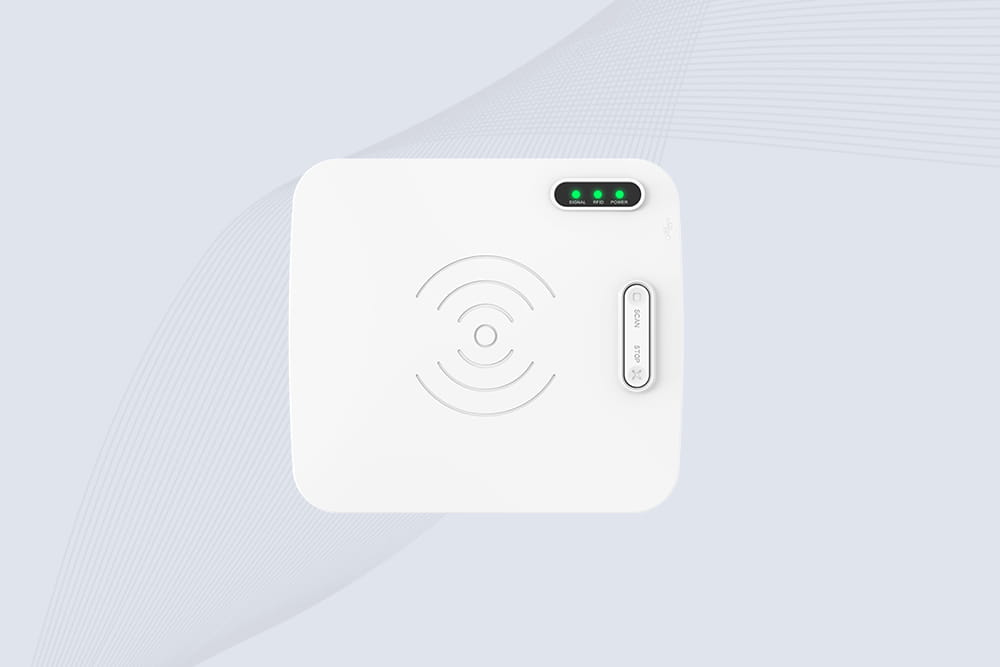
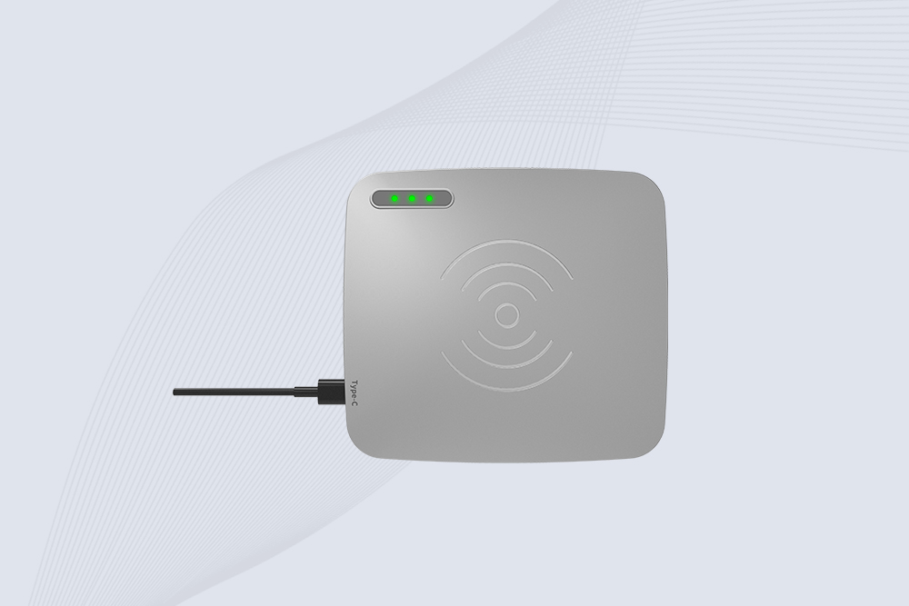
Desktop RFID reader: a controlled reading area
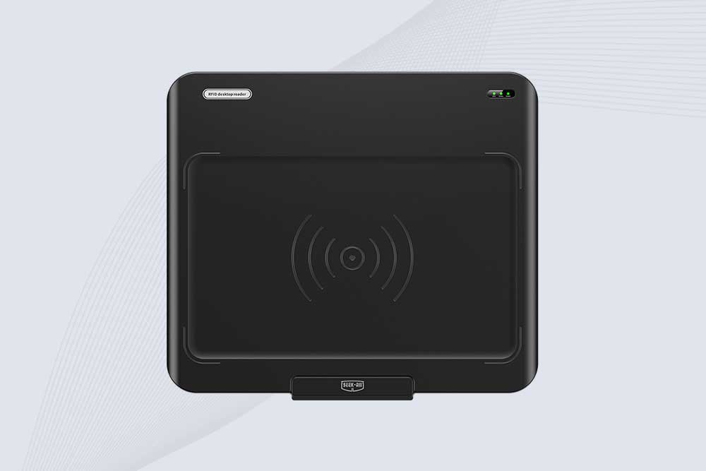
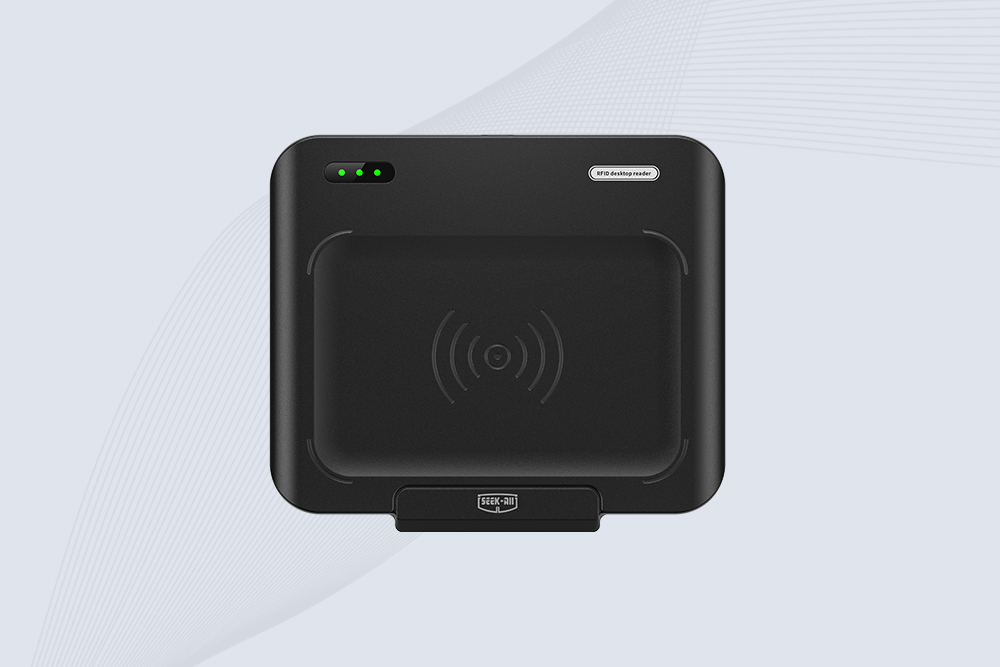
A desktop reader is useful when an operator presents a tag or card at a defined workstation. The diagram should show the tag close to the reader, the host connection, and the application used for reading, writing, or registration.
For example, a library workstation might use a desktop reader to register a book’s tag or associate an RFID identifier with a catalog record. This is different from a portal that reads many tagged items moving through a doorway.
Do not depict a short-range desktop reader as if it were designed to identify every tagged object across a warehouse. The intended reading distance, antenna design, tag type, and output power should match the product’s actual specifications.
Fixed UHF RFID reader: a defined reading zone
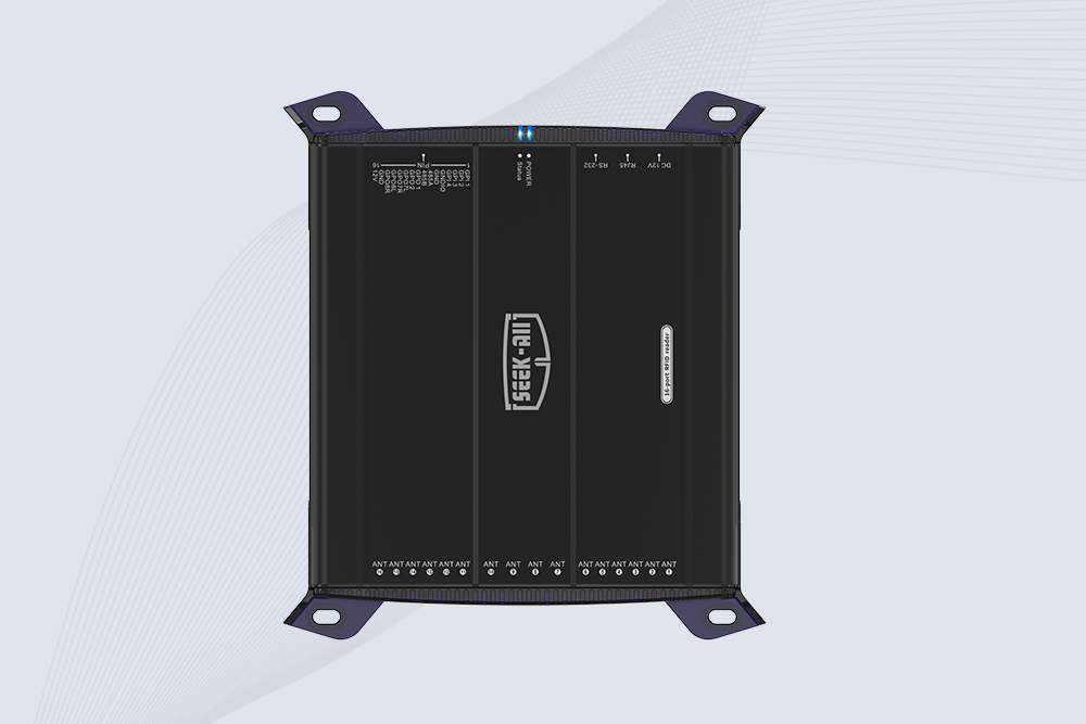
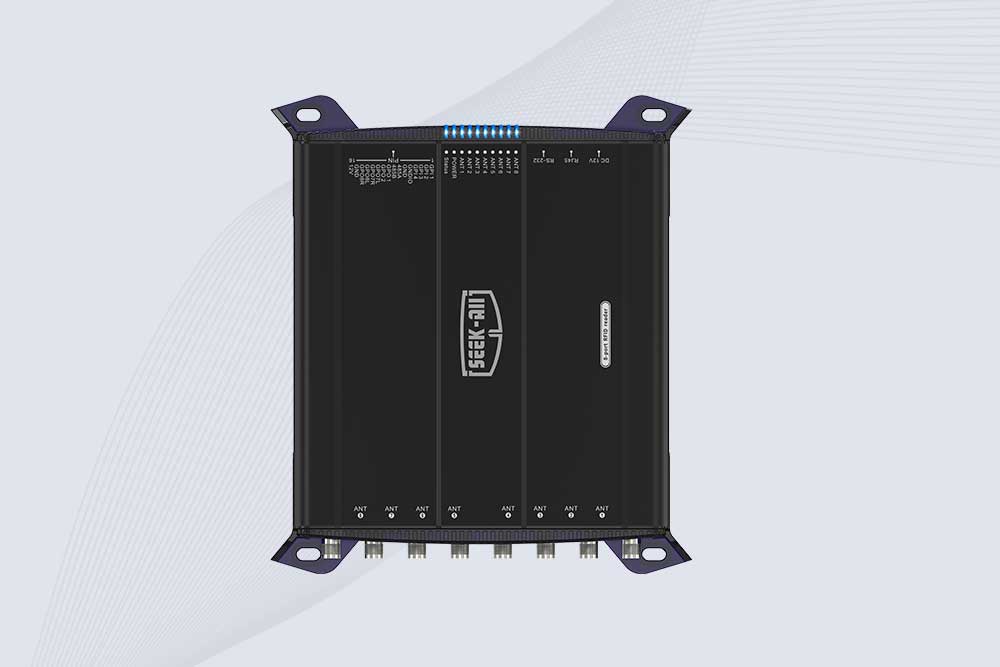
A fixed reader is commonly used when tags need to be identified without an operator presenting each item individually. Depending on the model, it may use an integrated antenna or one or more external antennas.
A Cykeo fixed-reader diagram could show tagged cartons passing a checkpoint, an industrial reader mounted beside the route, and a host application recording the resulting events. Where supported by the selected model, Ethernet or serial communication can be shown as the reader-to-host interface.
The diagram should not promise a specific read distance or read rate unless those values are verified against the exact model and tested configuration. Maximum laboratory or datasheet performance is not the same as guaranteed performance around metal racks, liquid-filled goods, or moving cartons.
RFID portal or tunnel: multiple antennas and moving goods
A portal diagram should show the physical route through which goods travel, the positions of the antennas, and the reader connected to the host system. If the installation uses a photoelectric sensor to detect an approaching carton, include it as a separate input rather than treating it as part of the RFID tag.
This matters when the system must distinguish a real passage from a tag that happens to be visible from the neighboring lane. A more complex portal may use several antennas, directional logic, or sensor inputs to improve event interpretation.
The final diagram should answer a specific question: What evidence does the system use to decide that an item has passed through this checkpoint?
Common Mistakes in an RFID System Diagram
A diagram can look convincing and still misrepresent how the system behaves. These are common errors to correct before publishing technical content or using a diagram in a project proposal.
Diagram mistake
Why it is misleading
Better approach
Showing a passive tag with its own battery as a requirement
Standard passive tags do not normally need a battery
Label the tag type; distinguish passive, battery-assisted passive, and active systems where relevant
Showing every tag being read at any distance
Read range depends on tag, reader, antenna, and environment
Show a defined reading zone and state that actual performance requires testing
Connecting the reader directly to a completed inventory result
A read does not automatically equal a valid business event
Include software validation and event processing
Treating RFID as a GPS location system
A normal RFID read identifies a tag within a reading zone; it does not inherently provide continuous coordinates
Show checkpoint-based detection or a separate real-time location architecture if needed
Leaving out the host connection
The diagram does not explain how tag data reaches the application
Label the actual supported interface, such as Ethernet, serial, or USB
Showing antennas without their coverage direction or purpose
Readers may capture unintended tags or miss tags in the target area
Indicate antenna placement, intended coverage, and the path of tagged objects
Using a product photograph as the entire technical diagram
A photograph may show equipment but not how data flows
Pair a realistic scene with a labeled architecture or process diagram
A related mistake is to label a reader’s maximum specified distance as the distance it will achieve in every installation. The effective read zone depends on the complete setup, including antenna characteristics, tag sensitivity, mounting, RF power, and nearby materials.
For technical publishing, keep product specifications and conceptual illustrations separate. A diagram can explain the architecture without promising a specific read rate or range.
How to Validate the Diagram Before Deployment
A diagram should be checked against the proposed installation before it is used as a design specification. This is particularly important when several systems exchange data or when RFID events trigger an automated action.
Use the following checklist:
Confirm the tag technology and supported RFID protocol.
Confirm the reader model and whether its antenna is integrated or external.
Verify the operating frequency for the deployment region.
Label the reader-to-host interface correctly.
Identify where filtering and duplicate handling take place.
Show any required sensors, controllers, or network equipment.
Define the business event generated by a successful read.
Test the intended tags with the actual mounting position, packaging, and movement speed.
Verify that the application records the correct item and event.
Document failure conditions, including missed reads and unexpected tag detections.
For example, an inventory receiving system should be tested with cartons positioned as they will be in actual operation. A tag that reads reliably when held directly in front of an antenna may behave differently when placed inside a densely packed carton or next to a metal surface.
The diagram is a model of the intended system. The commissioning test establishes whether the physical installation and software behave as that model predicts.
Frequently Asked Questions About how rfid works diagram
1. What is a how rfid works diagram?
A how rfid works diagram illustrates how an RFID tag communicates with a reader and how the captured data reaches software. It typically shows the tag, antenna, reader, host connection, and application. Depending on the use case, it may also include sensors, a conveyor, a portal, or an access-control system.
2. How does an RFID reader communicate with a tag?
In a typical passive UHF RFID system, the reader sends an RF interrogation signal through its antenna. The tag uses the received energy to respond by modulating the reflected signal, a method known as backscatter. The reader decodes the response and passes the captured data to the host system.
3. Does an RFID system need an internet connection?
Not always. An RFID reader needs a compatible way to communicate with its host or application, but that connection may be local. Some systems use Ethernet, serial communication, USB, or a local network. Internet access is needed only when the architecture requires remote services, cloud applications, or external data exchange.
4. Can RFID read multiple tags at once?
Yes. Compatible RFID systems can identify multiple tags within a reading zone, subject to protocol, reader configuration, tag placement, and environmental conditions. The actual number of tags read reliably depends on the installation. A system should be tested with the expected tag population and movement speed instead of relying on a theoretical maximum.
5. Does an RFID diagram show the exact location of an item?
Not necessarily. A standard RFID diagram usually shows a reading zone or checkpoint. When a tag is detected, the application can record that event and associate it with the reader’s configured location. Continuous positioning requires an architecture designed for that purpose; a conventional RFID tag read does not automatically provide GPS coordinates.
Explore the SSD-A07 UHF RFID antenna with 7 dBi gain, circular polarization, adjustable 840–960 MHz frequency, and 60°/75° beamwidth for stable RFID read/write performance.
SSD-A06 UHF RFID antenna with circular polarization, adjustable 840–960 MHz frequency, ≥4.5 dBi gain, and a compact directional design for RFID systems.
SSD-D3AL is a USB-HID UHF RFID reader with 0–30 cm reading, 0–15 cm writing, over 600 tags/s recognition, USB plug-and-play operation and OEM Logo customization.
SSD-D1AL is a compact USB UHF RFID reader with Impinj E710/X3M1 chipset, USB-HID, 600+ tags/s recognition, 4/8/16 antenna support and plug-and-play USB power.
SSD-R16L Multi-Channel RFID Infrastructure for Automated Inventory Management ✔️ 16-Port High-Density RFID Reading Equipped with 16 SMA antenna ports, SSD-R16L supports multi-antenna deployment for warehouses, retail stores, logistics, production lines, and large-area RFID identification. ✔️ High-Speed & Long-Range Performance With up to 33…
SSD-R8L 8-port UHF RFID reader with 33dBm output, up to 20m reading range and 600+ tags/s recognition. Ideal for warehouse, logistics, retail and asset tracking.
CYKEO CYKEO-D1LA USB RFID Reader is a compact desktop solution with near-field control for precise tag reading and encoding. Powered by USB, supporting ISO 18000-6C, and built for stable batch writing, this usb rfid tag reader fits retail, libraries, offices, and controlled RFID encoding tasks.
CYKEO CYKEO-D1L RFID scanner USB is a compact desktop UHF RFID scanner designed for short-range tag writing and verification. This usb rfid scanner supports batch encoding, stable 0–26 dBm output, and works across Windows, Linux, and Android systems.
CYKEO CYKEO-D1C USB RFID Card Reader is a near-field UHF desktop writer designed for secure, short-range tag encoding. With USB-C connectivity and stable 26 dBm output, this rfid reader usb c is ideal for badge issuance, label encoding, and controlled desktop RFID workflows.
CYKEO CYKEO-D2L RFID Reader USB is a compact desktop encoder built on the Impinj R500 chip. With near-field control and stable USB power, this usb rfid card reader delivers precise tag writing for offices, retail counters, and small-scale logistics encoding tasks.
CYKEO CYKEO-D3L USB RFID Tag Reader delivers stable UHF tag reading and writing for daily desktop and light industrial tasks. Designed for controlled short-range operation, this USB RFID Tag Reader works reliably with rfid tag and reader systems in libraries, tool tracking, and inventory registration.
The CYKEO CYKEO-D4L UHF RFID Tag Reader is a stable Desktop RFID Reader designed for accurate tag registration, borrowing, and return workflows. Built with the Impinj R2000 chip, this UHF RFID Tag Reader delivers controlled short-range reads for libraries, asset tracking, and inventory management environments.
The CYKEO CYKEO-D5L Desktop RFID Card Reader is a stable UHF RFID Card Reader designed for controlled short-range reading and writing. Built for libraries, tool rooms, and asset desks, this UHF RFID Card Reader supports dense tag handling, secure data processing, and easy USB integration.
The CYKEO CYKEO-D6L RFID Reader Writer is a heavy-duty Desktop RFID Reader designed for short-range, high-accuracy tag programming. Built for libraries, labs, and asset desks, this RFID Reader Writer supports batch processing, stable 33dBm output, and seamless integration with existing management systems.
Cykeo CYKEO-D8A embedded RFID badge reader offers 30+ tags/sec scanning, 20cm anti-crosstalk precision, and DC 12V power for unmanned stores, warehouses, and smart inventory systems.
Cykeo’s CYKEO-D8C UHF RFID gate reader achieves 200-tag/batch scanning with adjustable power control, ideal for retail inventory and smart warehouse management.
CYKEO Embedded RFID Modules are designed for compact industrial and IoT devices that require stable UHF performance. These UHF RFID Modules support global protocols, flexible power control, and reliable multi-tag reading for smart cabinets, production lines, and asset tracking systems.
CYKEO Embedded RFID Module is built for compact IoT and industrial devices that need stable UHF performance. This UHF module supports global protocols, low power operation, and reliable multi-tag reading for smart lockers, production lines, and always-on RFID systems.
CYKEO CYKEO-M1 drone rfid module is a compact UHF RFID reader module designed for drones and UAV platforms. It supports long-range aerial scanning, fast multi-tag reading, and stable performance in wind, vibration, and outdoor environments.
CYKEO CYKEO-M4 RC522 RFID Module is an industrial-grade UHF RFID reader with 4 ports, supporting ISO, EPC, and GB protocols. High-speed, accurate reading for IoT, automation, and warehouse applications.
CYKEO CYKEO-M8 Module RFID is an 8-port UHF R2000 RFID Module designed for high-density, multi-tag environments. Stable 33dBm output, ISO & GB protocol support, ideal for warehouses, factories, and automated systems.
CYKEO CYKEO-M16 RFID Module is a 16-port UHF RFID reader module based on the R2000 chipset. Designed for dense tag environments, it supports ISO and GB standards and delivers stable multi-antenna control for industrial automation.
The CYKEO CYKEO-M16L RFID Reader Module is a 16-channel UHF RFID core designed for dense tag environments. With adjustable 33dBm output, multi-protocol support, and stable multi-antenna control, this RFID Tag Reader Module fits industrial automation, warehouse systems, and large-scale IoT deployments.
CYKEO CYKEO-M8L module RFID is a compact industrial UHF module built for dense tag and multi-antenna environments. With 8 RF ports, adjustable 33 dBm output, and ISO & GB protocol support, it is widely used in factories, warehouses, and automated tracking systems.
CYKEOCYKEO-M4L UHF RFID Module is a compact 4-channel RFID tag reader module designed for dense tag environments. Supporting ISO and GB protocols, it delivers stable reads up to 10 meters for industrial and IoT systems.
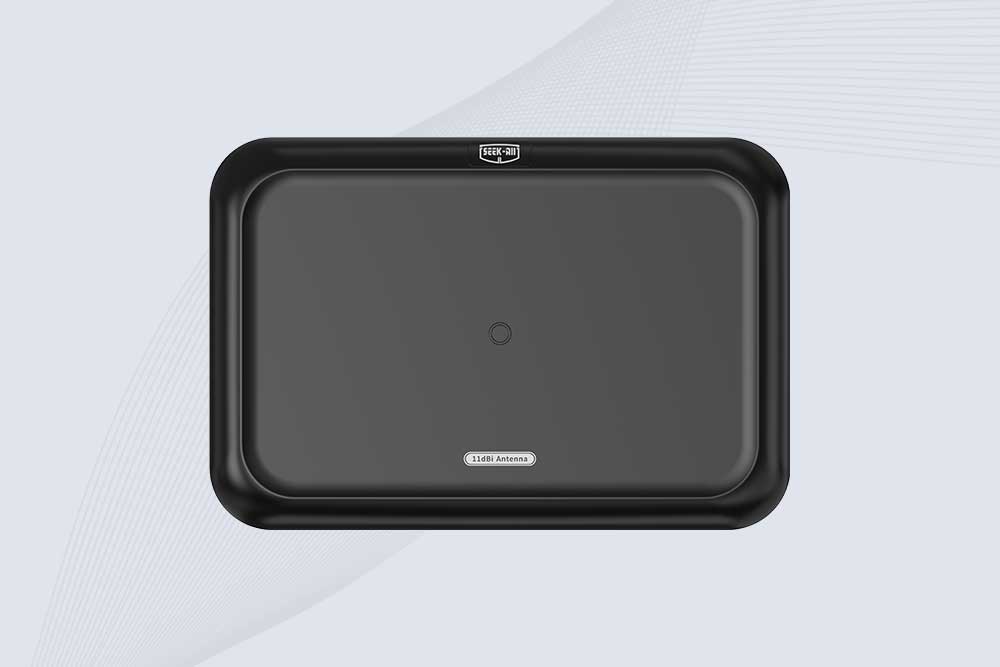
Cykeo CYKEO-A11 UHF RFID reader antenna delivers 11dBi gain, 840-960MHz frequency range, and IP65 ruggedness for retail, logistics, and industrial RFID systems. Features low VSWR and easy installation.
CYKEO Antenna RFID Reader delivers stable long-range UHF performance with a 10.5dBi directional design, built for warehouses, conveyor portals, and industrial RFID systems. This rfid reader antenna provides 20m+ read distance and rugged IP67 protection.
Cykeo CYKEO-A5B industrial Linear RFID Antenna delivers 5dBi gain, ≤1.5:1 VSWR, and IP65 rugged design for warehouse, production line, and logistics UHF systems.
Cykeo’s CYKEO-B12 Long Range RFID Antenna delivers 15m+ read range with 12dBi gain, IP65 rugged design, and global 840-960MHz UHF support. Ideal for warehouse/logistics asset tracking.
Cykeo CYKEO-B10 Long Distance RFID Antenna offers 10dBi gain, 840-960MHz frequency range, IP65 rating, and 20m+ coverage for logistics/warehousing/ETC systems. Low VSWR ensures stable signal transmission.
Cykeo CYKEO-A6 UHF RFID panel antenna features 6dBi gain, 840-960MHz broadband, IP65 metal-ready housing for logistics/smart retail. 18mm ultra-thin design with tool-free mounting.
Cykeo CK-A3 industrial antenna RFID UHF offers 5m+ tag detection, ≤1.3:1 VSWR, IP65 rugged design, and global UHF spectrum compatibility (840-960MHz) for warehouses, factories, and retail.
Cykeo CYKEO-B5 directional RFID antenna provides 5dBi gain with 60° narrow beamwidth for precise inventory tracking. IP65-rated, global UHF frequency support, and low VSWR.
Create your own high-performance DIY RFID antenna! 5dBi gain, 840-960MHz tunable, step-by-step guides. Compatible with Arduino, Raspberry Pi, and commercial UHF readers.
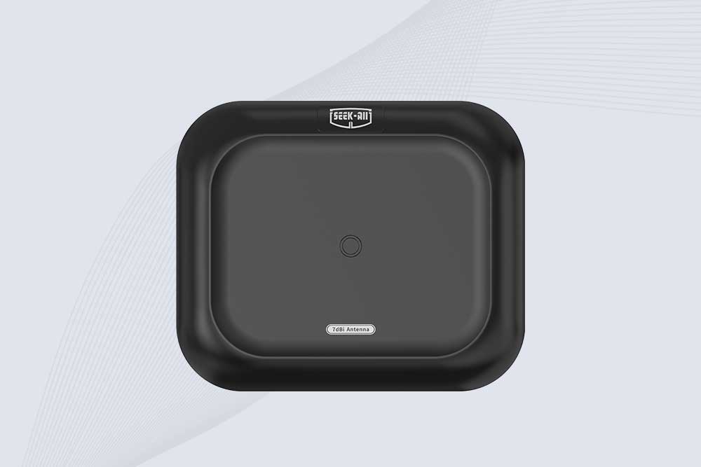
Cykeo CYKEO-A7 Flexible RFID Antenna features 840-960MHz wideband tuning, 7dBi gain, and IP68 rating for medical/retail/industrial curved surface deployments. 98% read accuracy with peel-and-stick installation.
Cykeo CYKEO-B5A industrial Passive RFID Antenna delivers 5dBi gain, 70° beamwidth, and -40°C~55°C operation for warehouses/smart cabinets. Compatible with Zebra/Impinj readers.
Cykeo’s CYKEO-A9B High Gain RFID Antenna delivers 15m+ read range with 9dBi amplification. Features IP54 rugged design, 840-960MHz bandwidth, and 80° beamwidth for warehouse/manufacturing RFID systems.
Cykeo’s enterprise-grade 8dbi Impinj RFID Antenna 10m+ read range with 840-960MHz tuning. Features IP65 housing, 1.4 VSWR, 35° beamwidth for retail/warehouse RFID systems.
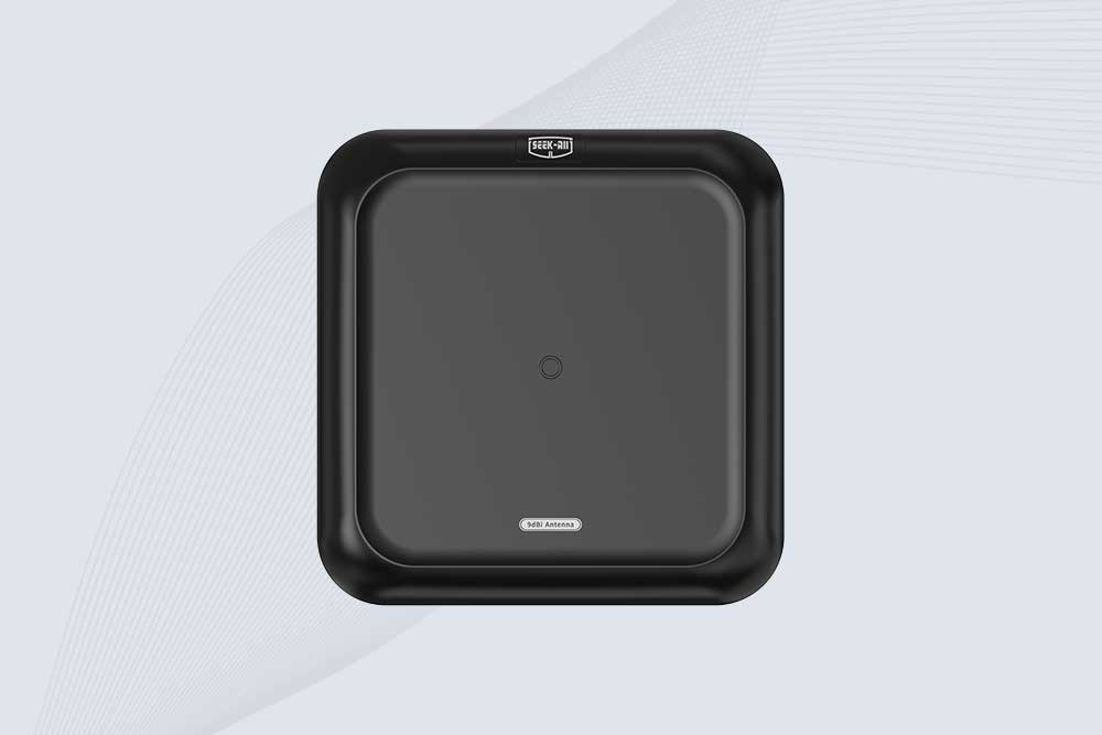
Cykeo CYKEO-A9 industrial UHF RFID antenna delivers 9dBi gain, 840-960MHz frequency range, and IP65 protection for warehouse/logistics/retail RFID systems. Features N-type connector and ≤1.3:1 VSWR.
CYKEO UHF RFID Antenna built for long-distance and industrial applications. This antenna rfid uhf delivers strong gain, outdoor durability, and reliable tag performance in warehouses, yards, and vehicle ID systems.
CYKEO Antenna RFID delivers reliable long-range UHF performance in warehouses, retail shelves, and cold-chain environments. This compact uhf rfid antenna provides stable reads with circular polarization and ultra-wide 840–960 MHz support, ideal for industrial tracking, smart shelves, and asset monitoring.
Cykeo’s CYKEO-C8 UHF RFID antennas delivers 8dBi gain, 840-960MHz full-band coverage, and IP65 ruggedness for manufacturing/warehouse RFID systems. Industrial RFID Antennas Features
Cykeo’s 8dBi UHF RFID antenna and reader kit delivers 10m+ range, 840-960MHz broadband, and IP65 ruggedness for factories, warehouses, and logistics. ISO 18000-6C & EPC Gen2 certified.
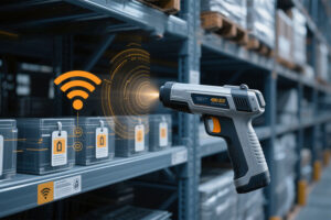
This article provides a comprehensive overview of rfid reader portable (handheld RFID readers), covering core functions, working principles, typical application scenarios, and key selection criteria, helping enterprises achieve more efficient tag ...
Discover actionable strategies to extend your RFID reader’s scanning range. Optimize antenna placement, reduce interference, and boost efficiency with Cykeo’s expert insights.
This article compares PoE and DC power for fixed-mount RFID readers, explaining their differences in cabling, power capacity, installation, and maintenance. ...
Learn how to optimize fixed RFID readers for high-speed conveyor belts. Discover Cykeo’s solutions for tag positioning, anti-collision settings, and real-time data capture.
 Cykeo RFID IoT Solution Products R&D Manufacturer