 Cykeo RFID IoT Solution Products R&D Manufacturer
How Far Away Read RFID? Complete Range Guide by Tag Type
365Wondering "how far away read RFID"? Discover exact read distances for LF, HF, UHF, and active tags. Factors affecting range and real-world performance with CYKEO.
MoreAll RFID Product
An RFID antenna works by converting electrical RF energy from a reader into electromagnetic waves and receiving the weak RF response from RFID tags. Its gain, polarization, frequency, radiation pattern, impedance, and physical position determine how efficiently energy reaches tags and how reliably the reader receives their responses.
An RFID antenna is the physical RF interface between the reader and the tag.
The reader generates an RF signal. The antenna launches that energy into space. When a tag enters the effective RF field, its rfid antenna couples with the signal. In passive UHF RFID, the tag uses received energy and responds through backscatter.
ISO/IEC 18000-63:2021 defines the UHF Type C air interface for RFID systems operating from 860 MHz to 960 MHz and specifies a passive-backscatter, reader-talks-first architecture. The reader transmits a continuous-wave RF signal; the tag changes the reflection characteristics of its antenna to return information
That makes the antenna more than an accessory.
It determines where the RF energy goes.
And just as importantly, where it does not go.
A warehouse portal, for example, may require a narrow and controlled reading corridor. A conveyor application may need a wider field. A handheld reader needs an antenna pattern suitable for an operator moving around shelves and cartons.
The same reader can behave very differently when the antenna changes.
An RFID antenna performs two jobs:
For a passive UHF system, this two-way relationship is critical.
The forward link needs enough energy to activate the tag and establish communication.
The return link is much weaker. The antenna must receive the tag’s backscattered response while the reader is operating in the same RF environment.
ISO/IEC 18000-63 specifies both forward and return link parameters, including frequency, modulation, data coding, bit rate and maximum effective isotropic radiated power.
This is why simply saying “the antenna has 9 dBi gain” does not fully describe an RFID antenna.
The installation still depends on:
Antenna gain describes how strongly an antenna concentrates RF energy in a particular direction.
RFID Journal explains antenna gain as a ratio comparing the field strength produced by an antenna with that of a reference antenna, with gain commonly expressed in decibels. Higher gain can provide greater reading distance in the antenna’s intended direction.
But higher gain does not simply mean “better.”
It often means more directional.
Consider two warehouse designs.
A portal antenna needs to project energy through a defined doorway. Higher directivity may help concentrate the field.
A shelf-monitoring application may need broader coverage. An overly narrow beam can create dead zones.
The design target is therefore not maximum gain.
It is the correct radiation pattern for the physical reading zone.
GS1 makes the same practical point: passive UHF read range depends on several factors, while the shape of the readable volume is strongly influenced by antenna directivity, gain, polarization and tag orientation.
Polarization describes the orientation of the electromagnetic field produced by the antenna.
For UHF RFID, the two common approaches are:
A linearly polarized antenna concentrates its electric field along a particular orientation. A tag antenna aligned favorably with that field can perform very well.
Rotate the tag.
Performance can change.
Circular polarization can be useful when tag orientation is unpredictable because the field rotates through different orientations. This can make it practical for portals, conveyors and moving products where tags may not remain consistently aligned.
There is a trade-off.
A circularly polarized antenna can have different effective performance characteristics compared with a linearly polarized antenna in a controlled orientation.
In actual deployment, I do not choose polarization from a product catalog alone.
I watch how the tagged object physically moves.
If cartons always pass label-forward, one solution may be ideal.
If workers throw mixed-orientation tools into a bin, another may be better.
An antenna does not produce a uniform spherical bubble of RF energy.
Its radiation pattern defines where energy is concentrated and how quickly field strength changes outside the main coverage area.
This becomes particularly important in fixed-reader installations.
Imagine a warehouse door with two storage racks immediately behind it.
If the antenna radiates too broadly, tags sitting on those racks may be detected even though they never passed through the door.
That creates false inventory events.
A carefully controlled pattern can reduce that problem.
| Characteristic | Practical effect |
|---|---|
| Gain | Concentrates energy and affects achievable range |
| Beamwidth | Defines the width of the main coverage area |
| Polarization | Influences sensitivity to tag orientation |
| Frequency | Determines RF operating characteristics |
| Impedance | Affects power transfer between reader and antenna |
| Front-to-back ratio | Helps control unwanted rear radiation |
| Connector/cable loss | Reduces delivered RF power |
| Physical orientation | Changes the actual field geometry |
This is why antenna placement should be treated as part of system engineering rather than installation decoration.
The antenna must be designed for the operating frequency of the RFID system.
For UHF Type C RFID, ISO/IEC 18000-63:2021 specifies the 860–960 MHz operating range.
GS1 separates RFID into LF, HF and UHF technologies and notes that radio waves behave differently at different frequencies. Its current guidance identifies UHF/RAIN RFID as operating in the 860–930 MHz range for fast asset identification, inventory and tracking applications.
This matters when selecting an antenna for international deployment.
The antenna, reader configuration and regional spectrum requirements need to be compatible.
Antenna specifications therefore should not be reduced to a single “RFID antenna” label.
The operating band is fundamental.
A technically excellent antenna can perform badly when mounted in the wrong location.
During deployment, I pay particular attention to:
The physical environment can create reflections and unexpected RF paths.
GS1 documentation specifically notes that environments containing substantial metal can create unwanted reflections of radio waves, making RFID reading more difficult or causing the wrong object to be read. It recommends testing the actual installation environment.
This is one of those details that rarely appears in a clean product photograph.
Antenna position is part of the RF circuit.
The interaction is easier to understand as a sequence:
1. Reader generates RF energy
The RFID reader produces the RF carrier within the applicable operating band.
2. Antenna radiates the signal
The reader antenna converts electrical RF power into electromagnetic energy.
3. Tag receives the field
The tag antenna couples with the incoming field.
4. Tag becomes active
For a passive UHF tag, harvested RF energy powers the tag IC.
5. Tag changes its antenna load
The chip controls the antenna’s reflection characteristics.
6. Antenna receives the backscatter
The reader antenna captures the modulated response.
7. Reader decodes the signal
Digital processing converts the RF response into tag data.
ISO describes this passive-backscatter process explicitly: the interrogator transmits a continuous-wave RF signal and the tag responds by modulating the reflection coefficient of its antenna.
The antenna is involved at both ends of that conversation.
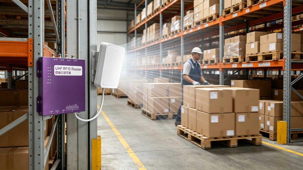
Multiple antennas can be useful.
They can also create a difficult RF environment if poorly configured.
A multi-antenna fixed rfid reader may switch between antennas to cover different sections of a portal, conveyor or shelf. The system needs to manage output power, timing and coverage so that antennas complement rather than unnecessarily interfere with one another.
The practical objective is not to illuminate the entire facility.
It is to create a predictable reading zone.
For example:
Receiving door → antenna field → tagged pallet → controlled read event
rather than:
Receiving door → antenna field → pallet → neighboring rack → adjacent doorway → unexpected read
This is where antenna directivity becomes a system-level feature.
The antenna is only one part of the link budget.
A failed read may originate from:
GS1 confirms that passive UHF read distance depends on reader power and interference, among other factors, and that the readable volume depends strongly on antenna gain, directivity, polarization and tag orientation.
This is why increasing reader power is not always the right fix.
Sometimes the better solution is moving the antenna 20–30 cm, changing polarization, selecting a different tag or narrowing the reading zone.
Small physical changes can produce large RF differences.
A serious antenna evaluation should happen with the actual tag and actual object.
I recommend recording at least:
| Test condition | What to observe |
|---|---|
| Single tag | Basic coupling and read performance |
| Multiple tags | Population handling |
| Different tag angles | Polarization sensitivity |
| Different distances | Coverage margin |
| Metal-mounted tag | Detuning and reflection effects |
| Liquid-containing object | Absorption and detuning |
| Moving tag | Dynamic performance |
| Antenna tilted | Coverage change |
| Neighboring antenna active | RF interaction |
| Actual production environment | Final system behavior |
ISO/IEC 18047-63:2023 defines conformance test methods for RFID tags and interrogators operating according to ISO/IEC 18000-63. The standard also notes that application-specific functionality can require additional criteria beyond general conformance testing.
That last point is important.
An antenna can meet its electrical specification and still be the wrong antenna for a particular warehouse.
The production environment is the final test.
Cykeo’s RFID reader solutions are designed to work with the antenna as part of the complete RF system rather than treating the antenna as an isolated accessory.
Applicable Cykeo UHF RFID platforms can support:
For example, the CYKEO-RA9L is an industrial-grade integrated UHF RFID reader with a 9 dBi antenna, designed for demanding fixed installations. Its integrated construction combines reader electronics and antenna characteristics into one field-deployable unit.
The CYKEO-M4L takes a different approach, integrating RF front-end and baseband digital processing into a compact module for OEM development.
These are different product architectures because the deployment problems are different.
For a complete portal, an integrated reader can simplify installation.
For an OEM product, a compact reader module can give the manufacturer more freedom over the final antenna and enclosure.
That distinction matters when designing the hardware around the application.
The antenna should be selected from the reading zone backward, not from the antenna specification forward.
For a fixed UHF RFID installation, the main choice is usually between linear-polarized and circular-polarized antennas.
| Antenna type | Main characteristic | Suitable situations |
|---|---|---|
| Linear polarization | Concentrated field orientation | Tags with predictable orientation |
| Circular polarization | More tolerant of changing tag orientation | Moving cartons, portals, mixed orientations |
| High-gain directional | Narrower, concentrated coverage | Long corridors, portals, controlled zones |
| Wide-beam antenna | Broader coverage | Shelves, workstations, short-range areas |
| Near-field antenna | Strong localized field | Desktop and close-proximity identification |
| Integrated RFID antenna | Reader and antenna combined | Compact fixed installations |
GS1 specifically identifies antenna directivity, gain, polarization and tag orientation as major factors determining the volume in which passive UHF tags can be read.
That last point is easy to underestimate.
A specification may say 9 dBi, but that number does not tell you whether the antenna will read the tags you actually care about.
The radiation pattern does. <h2>Linear vs. Circular Polarization in RFID</h2>
A linearly polarized antenna can perform extremely well when tag orientation is controlled.
Imagine labels attached to cartons with every label facing the same direction. The antenna and tag polarization can be deliberately aligned.
Now change the scene.
Workers place cartons at different angles. A pallet rotates. A garment swings on a hanger. A tool is dropped into a bin.
The polarization relationship becomes unpredictable.
Circular polarization can make the system more tolerant of changing tag orientation.
A published UHF RFID antenna study notes that reader antennas commonly use circular polarization, while polarization mismatch between circularly polarized reader antennas and linearly polarized tag antennas can introduce approximately 3 dB path loss.
That is not a trivial number in a marginal RF link.
It can be the difference between a comfortable operating margin and intermittent reads.
Higher antenna gain concentrates RF energy.
It does not magically create unlimited range.
A research study on UHF RFID reader antennas identifies high gain and high front-to-back ratio as important characteristics, while also pointing out the trade-off: higher gain requires the directional beam to be aligned with the tags being tracked.
This is where field installation becomes more interesting than the datasheet.
Suppose an antenna is mounted beside a loading door.
A narrow, high-gain pattern may produce excellent performance directly across the doorway. But if the pallet travels several feet to one side, the same antenna may become less effective.
A broader pattern may capture more positions but also increase unwanted reads.
The engineer is balancing coverage, selectivity and operating margin.
Not simply chasing maximum dBi.
RFID antennas can also be designed for different electromagnetic operating regions.
Near-field RFID is intended for controlled, close-proximity identification. The field is localized around the antenna, making it useful when the system needs to distinguish objects positioned very close to the reader.
Far-field RFID uses propagating electromagnetic waves and is the familiar architecture behind many UHF inventory and logistics systems.
Research published in the International Journal of Antennas and Propagation demonstrated an RFID reader antenna capable of both near-field and far-field operation, with measured far-field performance around 915 MHz and significant environmental effects when tags were placed near water or conducting surfaces.
This distinction matters for equipment design.
A desktop registration station does not need the same RF field geometry as a warehouse portal.
Trying to make one antenna architecture perform every job usually creates unnecessary compromises.
Antenna placement should be validated against the actual movement of tagged objects.
For a fixed installation, evaluate:
GS1’s pulp-product RFID guideline provides a useful example of application-specific antenna positioning: its test configuration specifies antenna height and orientation relative to the product rather than treating read distance as a single universal number.
That is a better engineering mindset.
Define the zone first.
Then make the antenna produce that zone.
Directional antennas can establish a defined passage through which tagged pallets and cartons are identified.
The objective is not maximum coverage.
It is controlled coverage.
Circular polarization can be useful when garments, packaged goods or handheld merchandise are not consistently oriented.
Metal tools require careful tag and antenna selection. On-metal RFID tags are often used because ordinary inlays can lose performance when mounted directly against conductive surfaces.
Antenna placement can be synchronized with product movement. The antenna should cover the expected tag position without unnecessarily illuminating neighboring lanes.
For large assets, antenna gain and radiation pattern become important because the physical distance and object orientation may vary considerably.
Metal changes the electromagnetic environment around an RFID antenna and tag.
The problem is not simply that “metal blocks RFID.”
Conductive surfaces can reflect electromagnetic waves and alter the impedance and radiation behavior of nearby antennas. GS1 specifically notes that metal can create reflections and diffraction, while specialized RFID tag constructions can improve performance on metallic objects.
For an industrial deployment, test the final mounted configuration.
A steel tool with an RFID tag attached is a different RF object from the same tag sitting on a workbench.
That distinction is often where field performance is won or lost.
Liquid creates another challenge.
Water and other liquids can absorb RF energy and affect antenna tuning. GS1 identifies liquids as a significant factor affecting passive UHF RFID performance.
For bottles, chemical containers, medical supplies or food packaging, test:
Do not qualify the tag only on an empty sample.
The product that eventually reaches the warehouse is the real RF test object.
Before selecting an antenna, define these parameters:
| Question | Engineering decision |
|---|---|
| What frequency is required? | Regional UHF band / applicable RFID standard |
| How far must tags be read? | Antenna gain and reader power |
| How predictable is tag orientation? | Linear or circular polarization |
| Is the reading zone narrow? | Directional antenna |
| Is broad coverage required? | Wider radiation pattern |
| Are objects metallic? | On-metal tag + antenna validation |
| Are liquids present? | Tag placement and RF testing |
| Are multiple readers nearby? | Antenna isolation and power planning |
| Must unwanted reads be prevented? | Beam control and shielding |
| Is the reader moving? | Antenna size, weight and pattern |
ISO/IEC 18000-63:2021 specifies UHF Type C RFID operation from 860–960 MHz, including forward and return link parameters, EIRP, modulation, coding and the multiple-tag collision-arbitration procedure.
As of 2026, ISO also lists a fourth edition of ISO/IEC 18000-63 as under development, so engineers working on new international products should verify the applicable regional and current standard requirements rather than relying on legacy documentation.
Cykeo approaches the antenna as part of the complete RFID RF chain.
That includes:
The CYKEO-RA9L combines a high-performance UHF RFID reader with an integrated 9 dBi antenna, creating a compact fixed-reader architecture for industrial installations.
Its integrated design is useful when installation simplicity matters.
The CYKEO-M4L takes another route. It combines an RF front end and baseband digital signal processing in a compact OEM module, allowing manufacturers to develop their own enclosure and antenna arrangement.
That difference is deliberate.
A warehouse portal and an embedded RFID product do not have the same RF constraints.
For OEM development, flexibility around the antenna can be more valuable than having a fixed integrated antenna.
For a field-deployed reader, controlled mechanical construction can be more valuable.

An RFID antenna transmits RF energy from the reader toward RFID tags and receives their responses. In passive UHF RFID, it is part of both the forward energy link and the return backscatter link.
It can, but not automatically. Higher gain generally concentrates energy into a more directional pattern. If the tag is outside that useful pattern, the additional gain may provide little practical benefit.
Neither is universally better. Linear polarization can be highly effective when tag orientation is controlled. Circular polarization is often more tolerant when tag orientation changes during movement.
There is no universal number. A small identification point may require one antenna, while a warehouse portal may use multiple antennas to control coverage from different directions.
Yes. The antenna and tag must be selected and positioned for the environment. Metal can alter RF propagation and create reflections, so actual installation testing is important.
Yes. Antenna height, angle, polarization, surrounding structures and tag orientation all influence the usable reading volume. GS1 specifically identifies antenna directivity, gain, polarization and tag orientation as important factors.
There is no single best model. A warehouse portal usually benefits from a directional antenna selected according to the required read zone, tag orientation, portal dimensions, reader power and surrounding RF environment.
It converts electrical RF power into electromagnetic energy and receives the weak response from RFID tags. Its gain, polarization, radiation pattern, frequency and installation position determine where tags can be energized and detected.
The antenna is therefore not just the component attached to the reader.
It shapes the physical boundary of the RFID system.
In a controlled portal, that boundary should be deliberate. In a handheld reader, it should support the operator’s movement. Around metal, the antenna and tag must be treated as a combined RF problem.
For Cykeo RFID deployments, the useful question is rarely “How much range does this antenna have?”
A better question is:
“What reading zone does this antenna create under the exact conditions where the system will operate?”
That is the engineering question behind how does rfid antenna work.
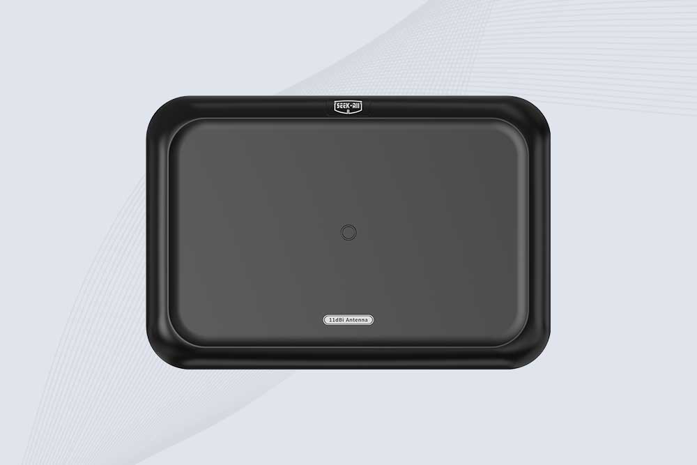
SSD-A11 UHF RFID antenna features 840–960 MHz adjustable frequency, ≥10.5 dBi gain, circular polarization and 50Ω impedance for fixed RFID systems.
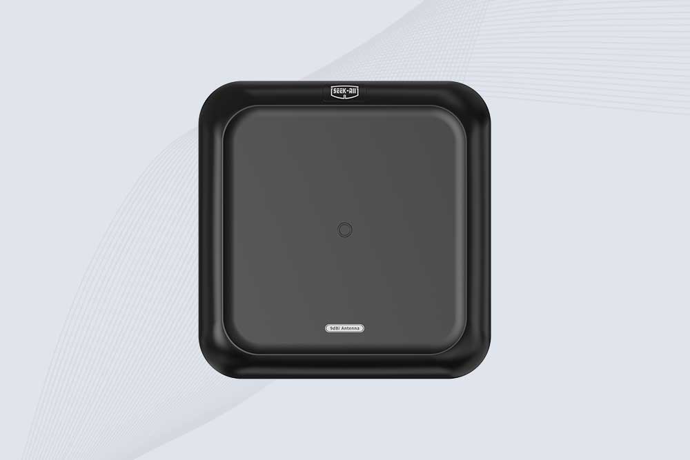
SSD-A09 is a 9 dBi UHF RFID antenna with 840–960 MHz adjustable frequency, circular polarization, 50Ω impedance and directional 60° × 60° coverage.
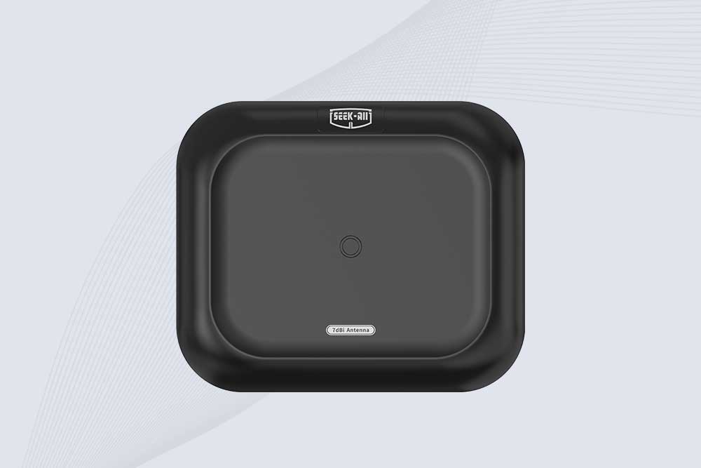
Explore the SSD-A07 UHF RFID antenna with 7 dBi gain, circular polarization, adjustable 840–960 MHz frequency, and 60°/75° beamwidth for stable RFID read/write performance.

SSD-A06 UHF RFID antenna with circular polarization, adjustable 840–960 MHz frequency, ≥4.5 dBi gain, and a compact directional design for RFID systems.
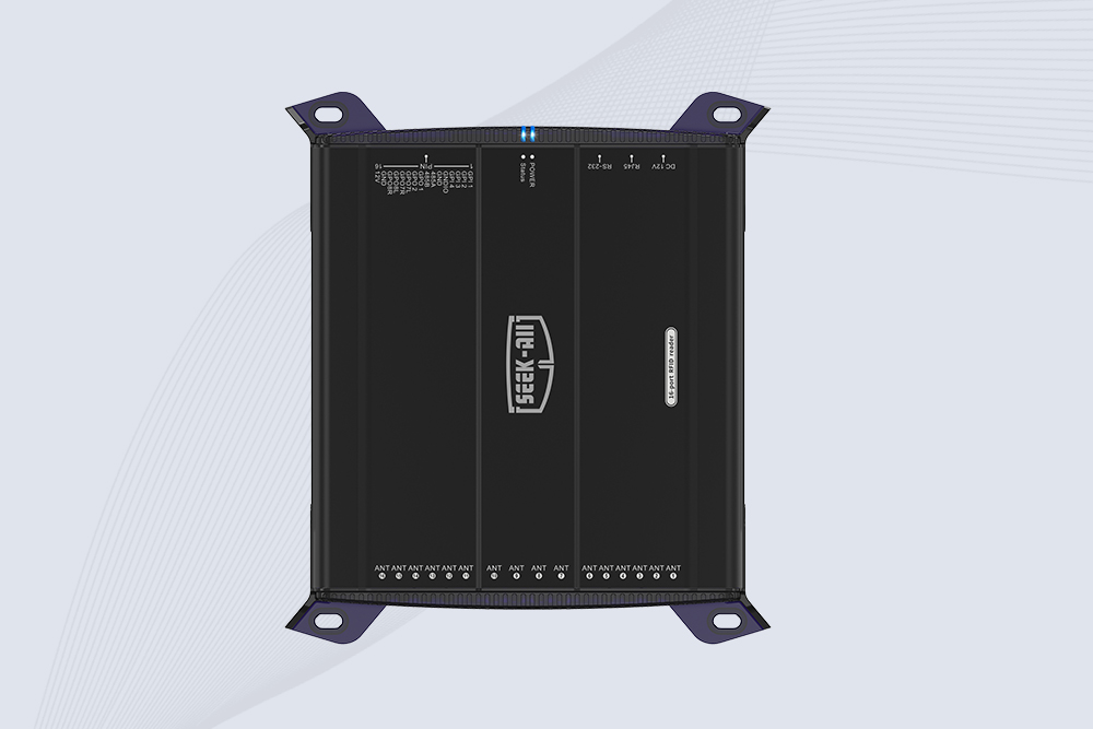
SSD-R16L Multi-Channel RFID Infrastructure for Automated Inventory Management ✔️ 16-Port High-Density RFID Reading Equipped with 16 SMA antenna ports, SSD-R16L supports multi-antenna deployment for warehouses, retail stores, logistics, production lines, and large-area RFID identification. ✔️ High-Speed & Long-Range Performance With up to 33…
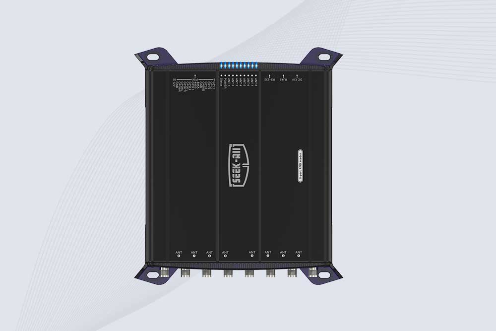
SSD-R8L 8-port UHF RFID reader with 33dBm output, up to 20m reading range and 600+ tags/s recognition. Ideal for warehouse, logistics, retail and asset tracking.
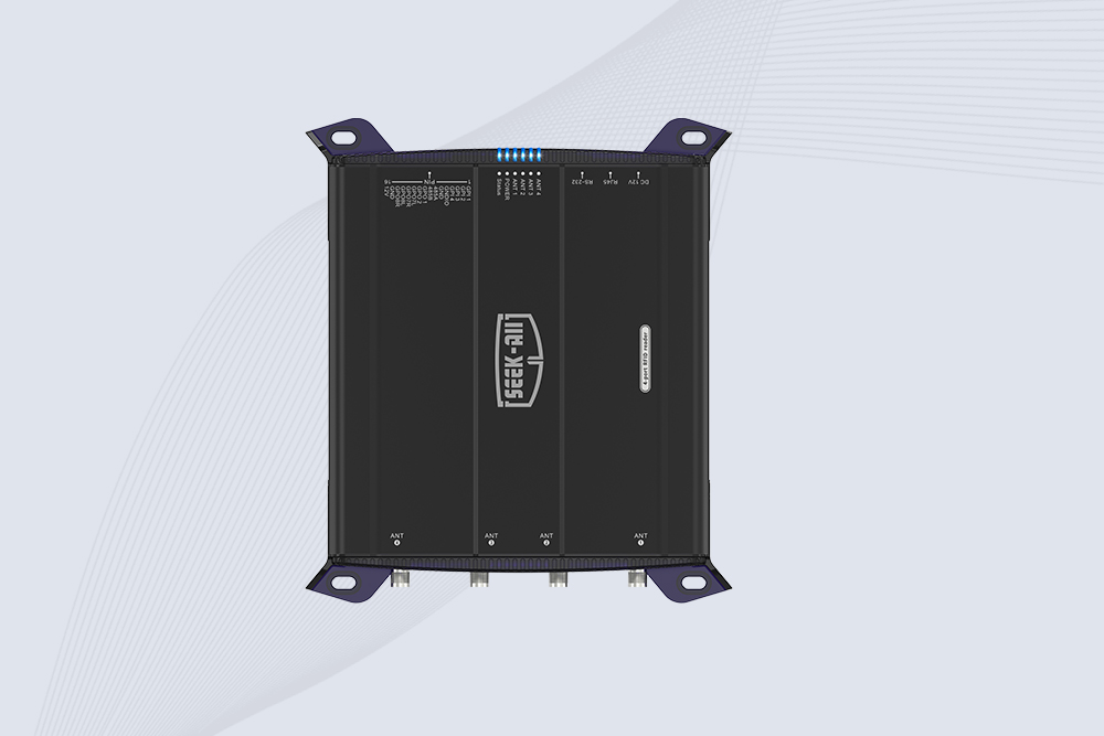
SSD-R4L is a 4-port UHF RFID fixed reader with 33dBm output power, up to 20m reading range, EPC C1G2 support and 600+ tags/s reading speed.
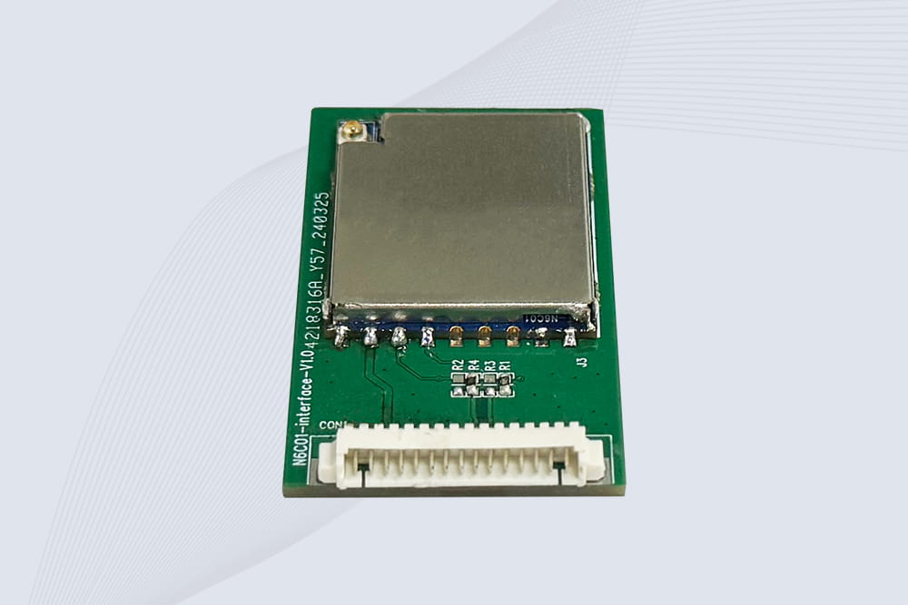
CYKEO Embedded RFID Modules are designed for compact industrial and IoT devices that require stable UHF performance. These UHF RFID Modules support global protocols, flexible power control, and reliable multi-tag reading for smart cabinets, production lines, and asset tracking systems.
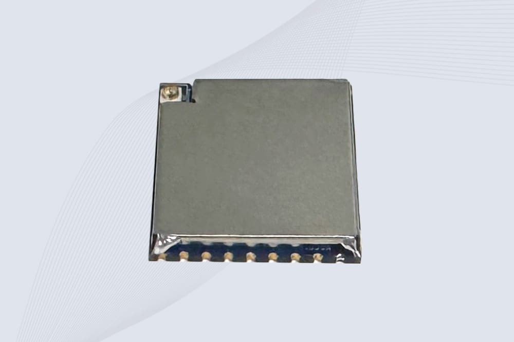
CYKEO Embedded RFID Module is built for compact IoT and industrial devices that need stable UHF performance. This UHF module supports global protocols, low power operation, and reliable multi-tag reading for smart lockers, production lines, and always-on RFID systems.
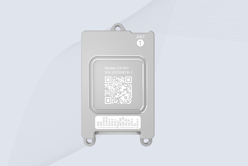
CYKEO CYKEO-M1 drone rfid module is a compact UHF RFID reader module designed for drones and UAV platforms. It supports long-range aerial scanning, fast multi-tag reading, and stable performance in wind, vibration, and outdoor environments.
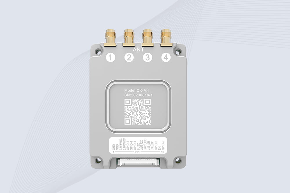
CYKEO CYKEO-M4 RC522 RFID Module is an industrial-grade UHF RFID reader with 4 ports, supporting ISO, EPC, and GB protocols. High-speed, accurate reading for IoT, automation, and warehouse applications.
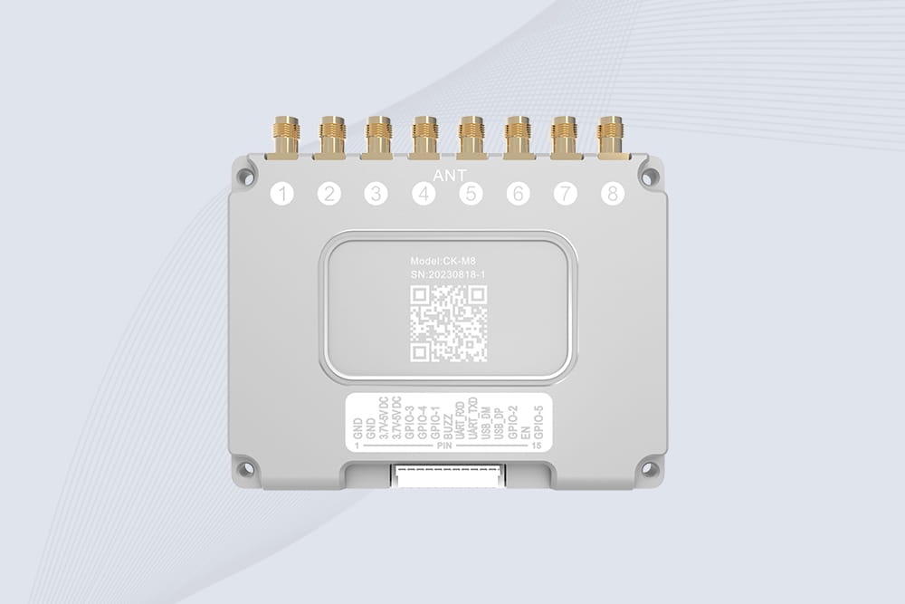
CYKEO CYKEO-M8 Module RFID is an 8-port UHF R2000 RFID Module designed for high-density, multi-tag environments. Stable 33dBm output, ISO & GB protocol support, ideal for warehouses, factories, and automated systems.
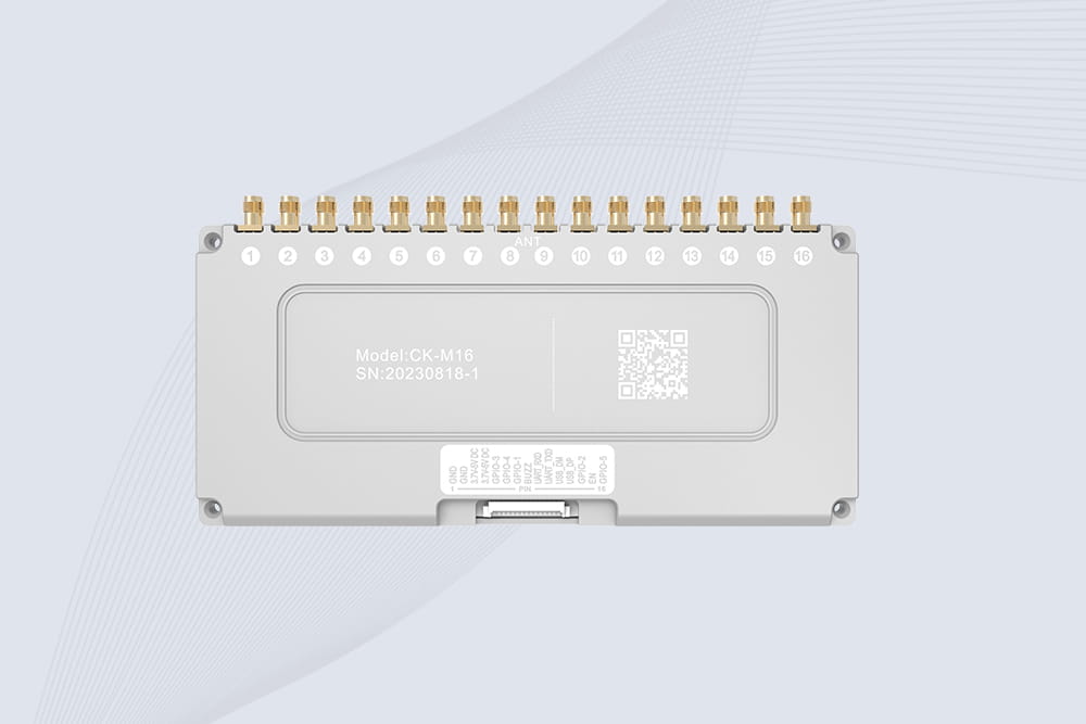
CYKEO CYKEO-M16 RFID Module is a 16-port UHF RFID reader module based on the R2000 chipset. Designed for dense tag environments, it supports ISO and GB standards and delivers stable multi-antenna control for industrial automation.
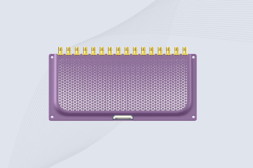
The CYKEO CYKEO-M16L RFID Reader Module is a 16-channel UHF RFID core designed for dense tag environments. With adjustable 33dBm output, multi-protocol support, and stable multi-antenna control, this RFID Tag Reader Module fits industrial automation, warehouse systems, and large-scale IoT deployments.
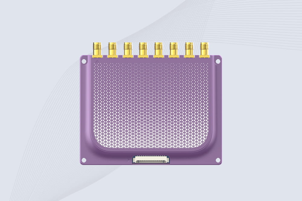
CYKEO CYKEO-M8L module RFID is a compact industrial UHF module built for dense tag and multi-antenna environments. With 8 RF ports, adjustable 33 dBm output, and ISO & GB protocol support, it is widely used in factories, warehouses, and automated tracking systems.
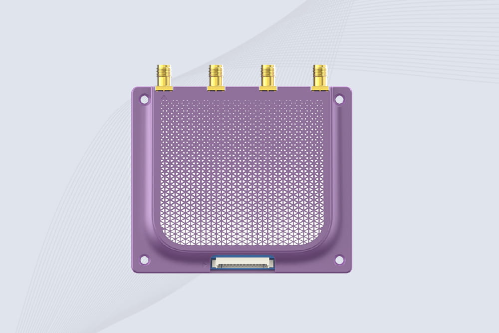
CYKEOCYKEO-M4L UHF RFID Module is a compact 4-channel RFID tag reader module designed for dense tag environments. Supporting ISO and GB protocols, it delivers stable reads up to 10 meters for industrial and IoT systems.
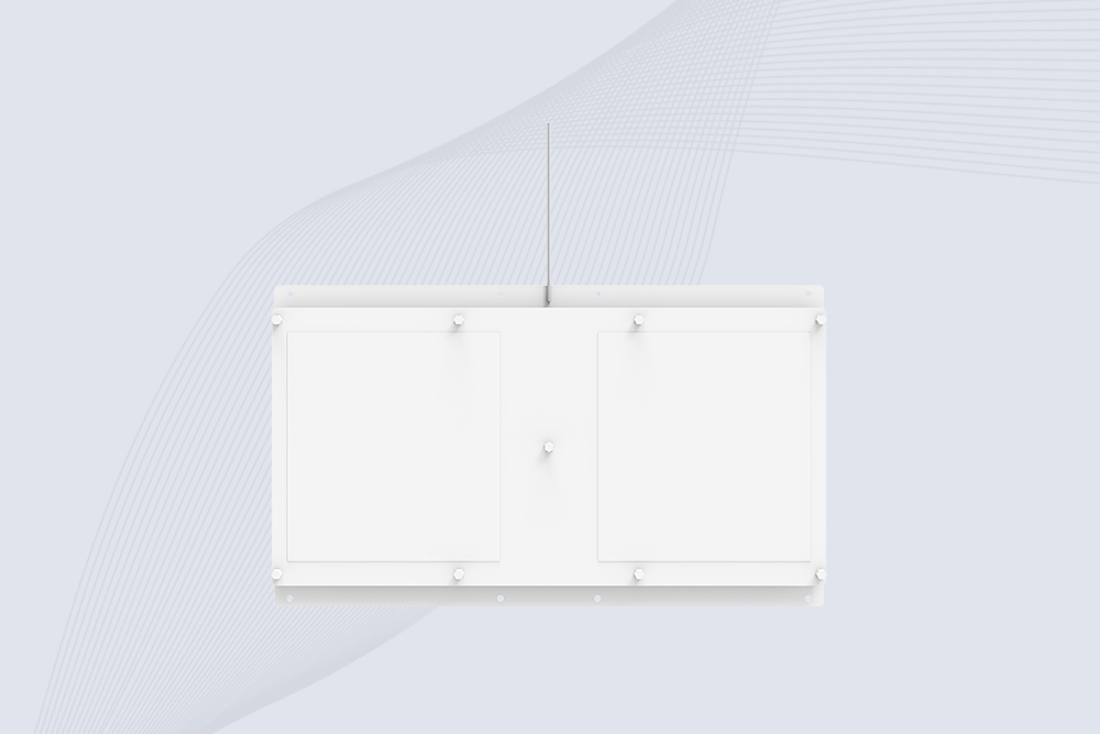
Cykeo CYKEO-A11 UHF RFID reader antenna delivers 11dBi gain, 840-960MHz frequency range, and IP65 ruggedness for retail, logistics, and industrial RFID systems. Features low VSWR and easy installation.

CYKEO Antenna RFID Reader delivers stable long-range UHF performance with a 10.5dBi directional design, built for warehouses, conveyor portals, and industrial RFID systems. This rfid reader antenna provides 20m+ read distance and rugged IP67 protection.

Cykeo CYKEO-PHF3 industrial HF RFID Antenna offers 24-point dynamic tracking, ISO 14443A/15693 protocols, metal-environment stability for archives/libraries/manufacturing.

Cykeo CYKEO-A5B industrial Linear RFID Antenna delivers 5dBi gain, ≤1.5:1 VSWR, and IP65 rugged design for warehouse, production line, and logistics UHF systems.

Cykeo’s CYKEO-B12 Long Range RFID Antenna delivers 15m+ read range with 12dBi gain, IP65 rugged design, and global 840-960MHz UHF support. Ideal for warehouse/logistics asset tracking.
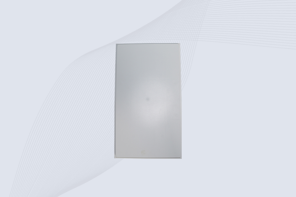
Cykeo CYKEO-B10 Long Distance RFID Antenna offers 10dBi gain, 840-960MHz frequency range, IP65 rating, and 20m+ coverage for logistics/warehousing/ETC systems. Low VSWR ensures stable signal transmission.
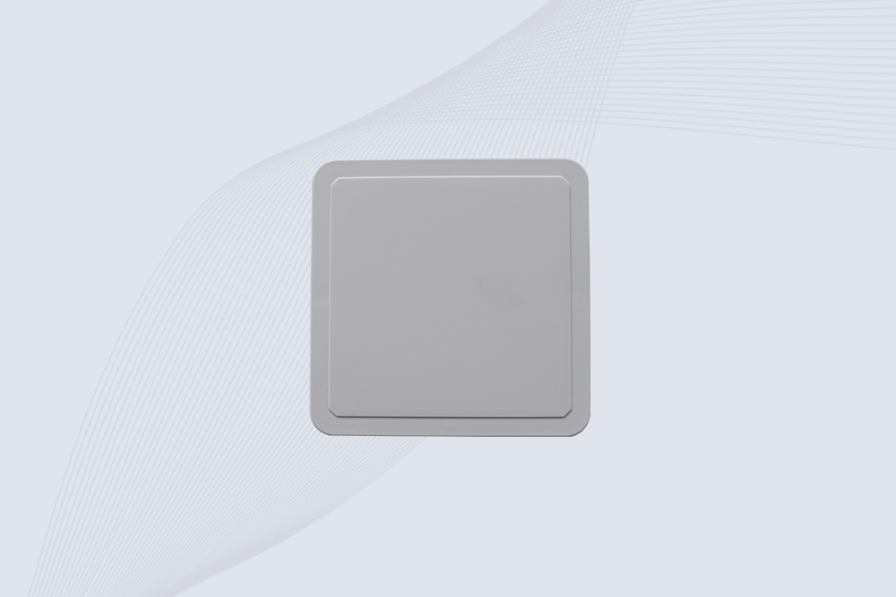
Cykeo CYKEO-A6 UHF RFID panel antenna features 6dBi gain, 840-960MHz broadband, IP65 metal-ready housing for logistics/smart retail. 18mm ultra-thin design with tool-free mounting.

Cykeo CK-A3 industrial antenna RFID UHF offers 5m+ tag detection, ≤1.3:1 VSWR, IP65 rugged design, and global UHF spectrum compatibility (840-960MHz) for warehouses, factories, and retail.
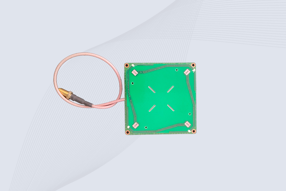
Cykeo CYKEO-B5 directional RFID antenna provides 5dBi gain with 60° narrow beamwidth for precise inventory tracking. IP65-rated, global UHF frequency support, and low VSWR.
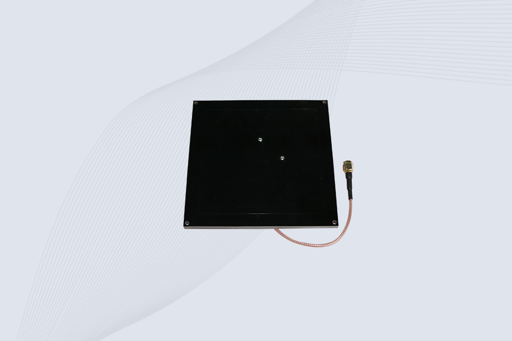
Create your own high-performance DIY RFID antenna! 5dBi gain, 840-960MHz tunable, step-by-step guides. Compatible with Arduino, Raspberry Pi, and commercial UHF readers.
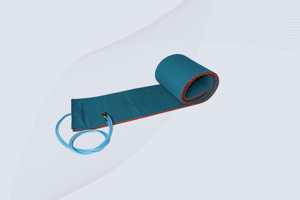
Cykeo CYKEO-A7 Flexible RFID Antenna features 840-960MHz wideband tuning, 7dBi gain, and IP68 rating for medical/retail/industrial curved surface deployments. 98% read accuracy with peel-and-stick installation.

Cykeo CYKEO-B5A industrial Passive RFID Antenna delivers 5dBi gain, 70° beamwidth, and -40°C~55°C operation for warehouses/smart cabinets. Compatible with Zebra/Impinj readers.
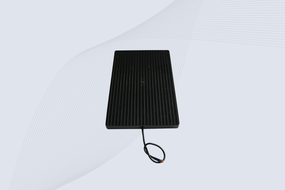
Cykeo’s CYKEO-A9B High Gain RFID Antenna delivers 15m+ read range with 9dBi amplification. Features IP54 rugged design, 840-960MHz bandwidth, and 80° beamwidth for warehouse/manufacturing RFID systems.

Cykeo’s enterprise-grade 8dbi Impinj RFID Antenna 10m+ read range with 840-960MHz tuning. Features IP65 housing, 1.4 VSWR, 35° beamwidth for retail/warehouse RFID systems.
Cykeo CYKEO-A9 industrial UHF RFID antenna delivers 9dBi gain, 840-960MHz frequency range, and IP65 protection for warehouse/logistics/retail RFID systems. Features N-type connector and ≤1.3:1 VSWR.
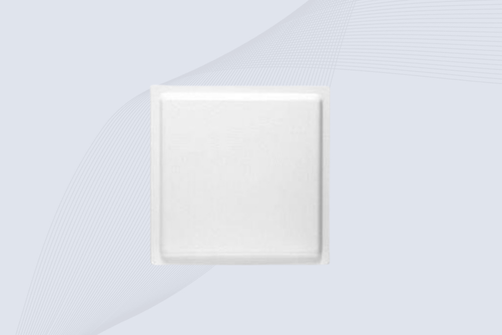
CYKEO UHF RFID Antenna built for long-distance and industrial applications. This antenna rfid uhf delivers strong gain, outdoor durability, and reliable tag performance in warehouses, yards, and vehicle ID systems.
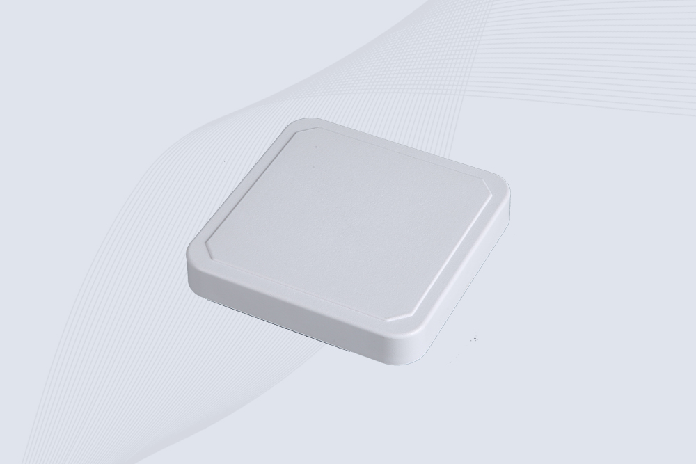
CYKEO Antenna RFID delivers reliable long-range UHF performance in warehouses, retail shelves, and cold-chain environments. This compact uhf rfid antenna provides stable reads with circular polarization and ultra-wide 840–960 MHz support, ideal for industrial tracking, smart shelves, and asset monitoring.
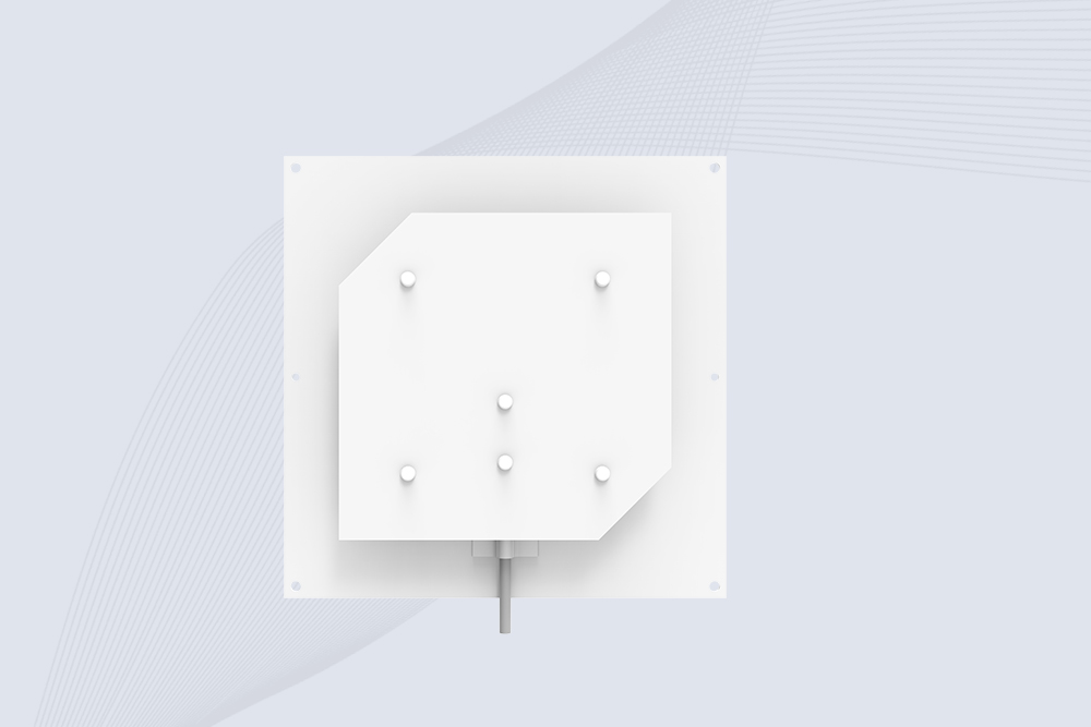
Cykeo’s CYKEO-C8 UHF RFID antennas delivers 8dBi gain, 840-960MHz full-band coverage, and IP65 ruggedness for manufacturing/warehouse RFID systems. Industrial RFID Antennas Features
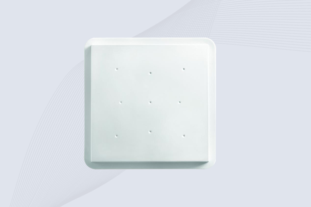
Cykeo’s 8dBi UHF RFID antenna and reader kit delivers 10m+ range, 840-960MHz broadband, and IP65 ruggedness for factories, warehouses, and logistics. ISO 18000-6C & EPC Gen2 certified.
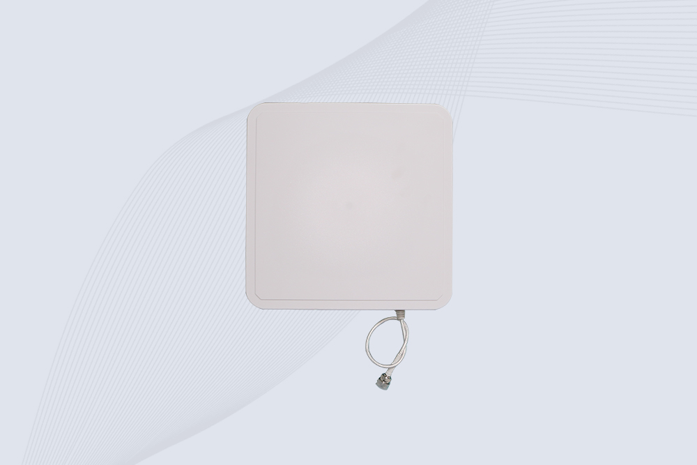
Cykeo CYKEO-A9A industrial UHF RFID reader and antenna kit delivers 10m range, 500 tags/sec, IP65 ruggedness for manufacturing/logistics. Supports EPC Gen2, ISO18000-6C.
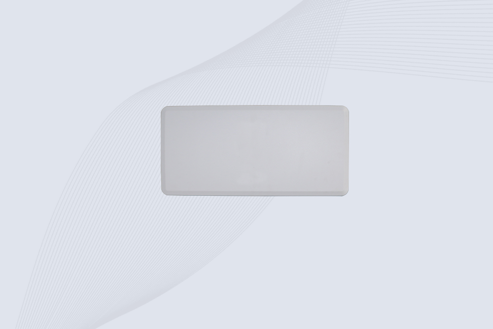
Cykeo’s CYKEO-A12C UHF Large RFID Antenna delivers 12dBi gain, 840-960MHz global frequency, IP65 ruggedness for logistics/warehousing/automotive. 40° beamwidth ensures stable 15m+ tag reads.

CYKEO Near Field RFID Antenna provides precise 5–30 cm reading for shelves, cabinets, and workstations. This compact rfid shelf antenna delivers stable short-range performance around metal and clutter, ideal for pharmacies, libraries, and electronics sorting.
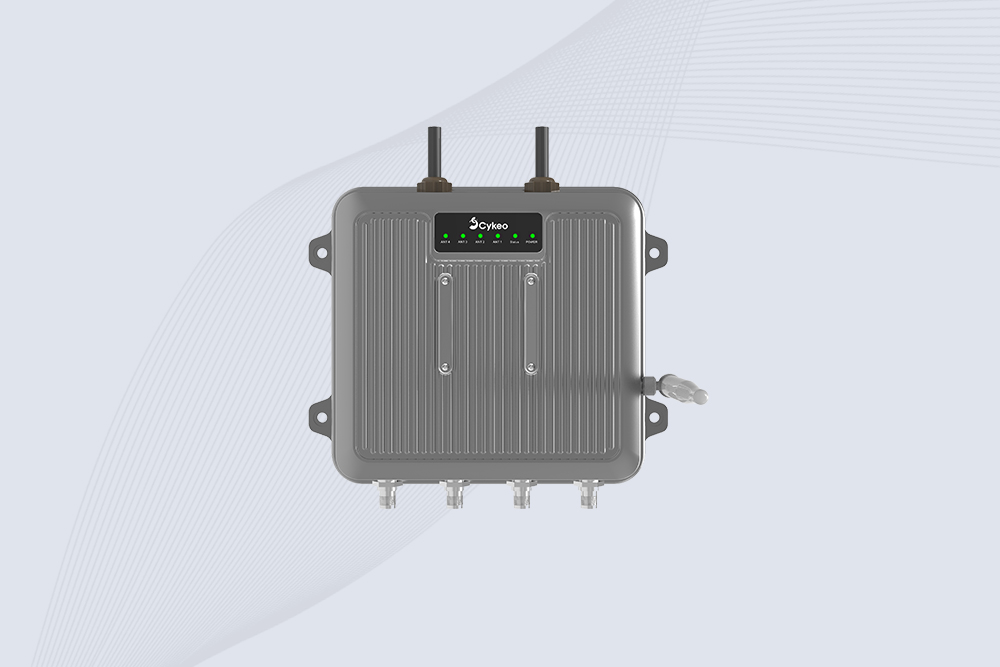
Cykeo CYKEO-C1 industrial Forklift RFID Reader features 20m read range, 600 tags/sec scanning, Impinj R2000 chipset, and IP67 rugged design. Ideal for warehouse logistics and manufacturing. Supports ISO 18000-6C/6B protocols.
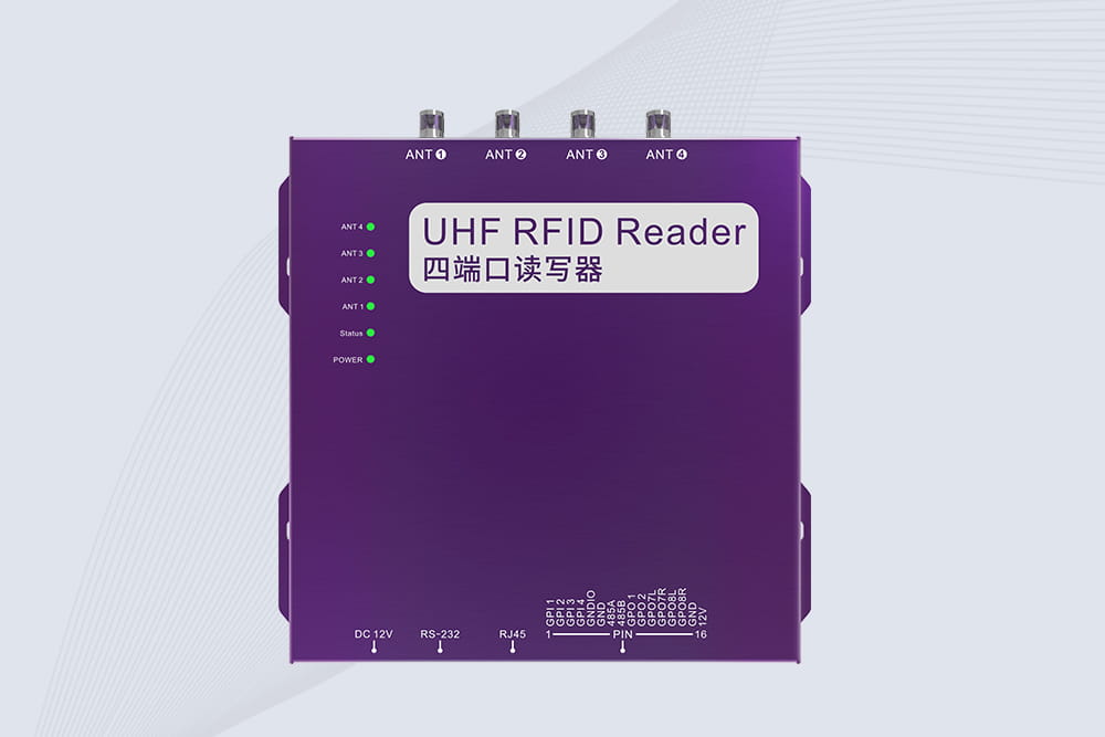
Cykeo CYKEO-R4 industrial UHF RFID Fixed Reader features 4 TNC ports, 400+ tags/sec speed, IP67 housing, and global frequency compliance for vehicle inspection, smart warehouse, and asset management systems.
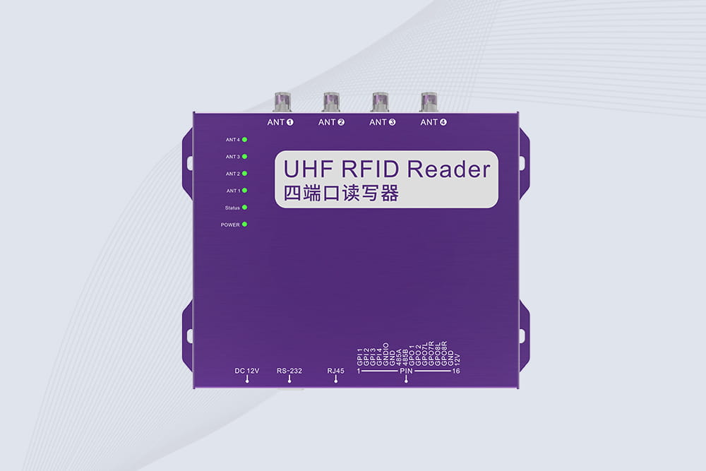
Cykeo’s CYKEO-R4L 4-port Fixed UHF RFID Reader delivers 400 tags/sec scanning, ISO 18000-6C compliance, and IP65 protection. Ideal for warehouse automation, manufacturing WIP tracking, and logistics management.
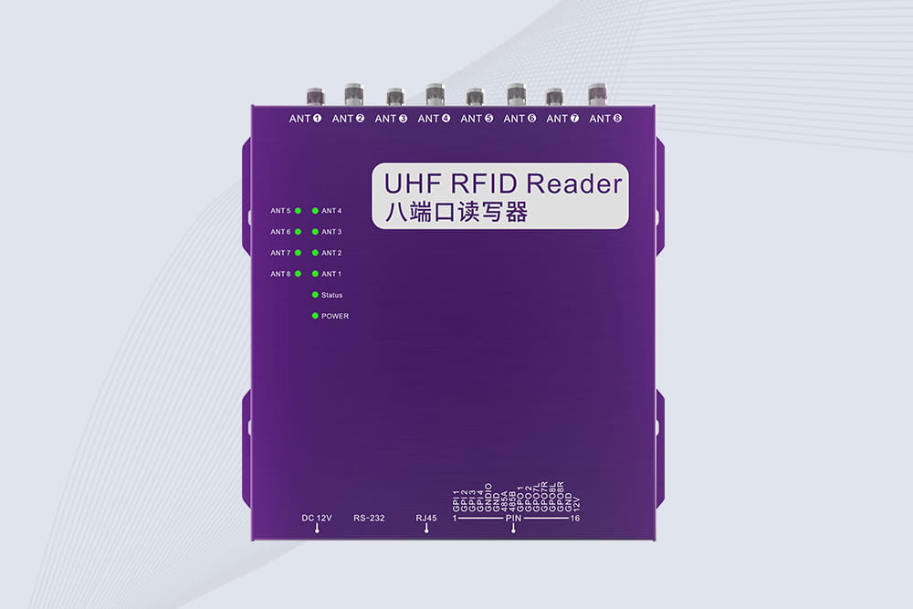
CYKEO CYKEO-R8L Fixed RFID Reader with 8-port UHF design, Impinj-based RF core and up to 20m read range. An industrial Fixed RFID Reader for vehicle inspection, warehouse portals, smart manufacturing lines and secure access checkpoints.
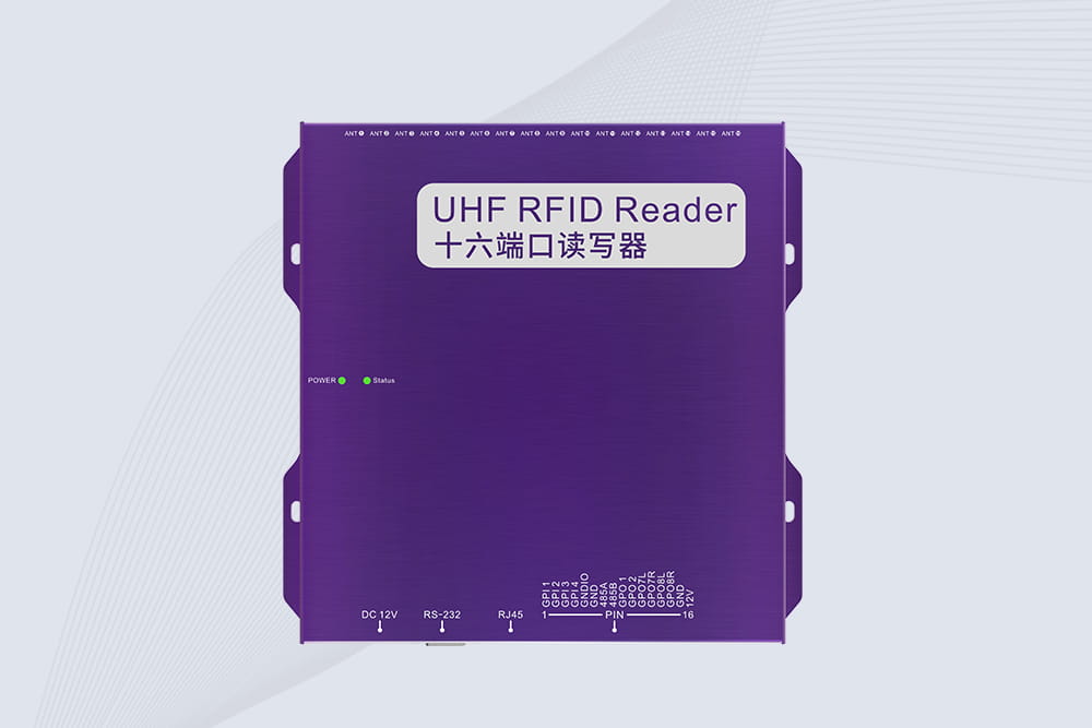
RFID Fixed Reader from CYKEO – the CYKEO-R16L 16-port UHF fixed reader for warehouses, smart cabinets, and production lines. Long-range, multi-tag reading, stable performance for 24/7 industrial use.

Wondering "how far away read RFID"? Discover exact read distances for LF, HF, UHF, and active tags. Factors affecting range and real-world performance with CYKEO.
More
Discover how fixed RFID readers enhance manufacturing efficiency. Learn key benefits like real-time tracking, reduced downtime, and improved asset management.
More
rfid medical cabinet price, rfid for hospitals cost, hospital rfid system cost, medical cabinet rfid price
More
Wondering "RFID is what?" CYKEO breaks down the basics of radio frequency identification, how passive tags work, and where you use them every day.
More