 Cykeo RFID IoT Solution Products R&D Manufacturer
OEM RFID Reader Module: How Companies Build Custom RFID Devices
132Learn how companies use OEM RFID reader modules to build custom RFID devices for smart cabinets, industrial automation, warehouse systems, and medical equipment tracking.
MoreAll RFID Product
Access control systems aren’t that complicated. It’s basically a card reader + a door lock + a power supply + some wires. Connect them correctly, and it works. Many people think you must hire a professional, but as long as you understand a few basic concepts, you can follow a wiring diagram and do it yourself.
Here are the key components you’ll need:
The wiring logic is actually simple. For the power lines, red goes to positive and black to ground—just make sure the 12V supply is stable.
For data transmission, most readers use the Wiegand protocol: green wire is Data0, white wire is Data1, connect them to the corresponding terminals on the controller.
The door lock is controlled via the controller’s relay. Common connections are COM and NO/NC. Normally locked, the relay triggers when a card is swiped, cuts the power, and the door opens.
The exit button is simpler: connect it to COM and NO. Pressing it sends a signal to unlock.
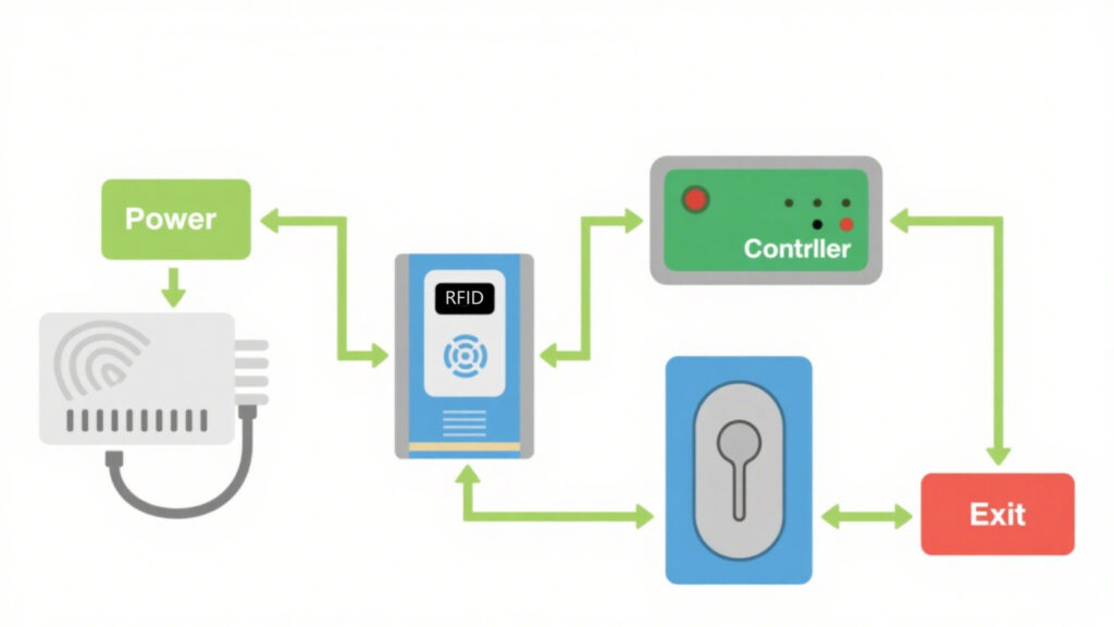
A few details can save a lot of trouble:
When debugging, don’t connect everything at once:
If swiping doesn’t work, check the power first, then make sure the data wires aren’t reversed. Green and white wires for Wiegand are commonly mixed up.
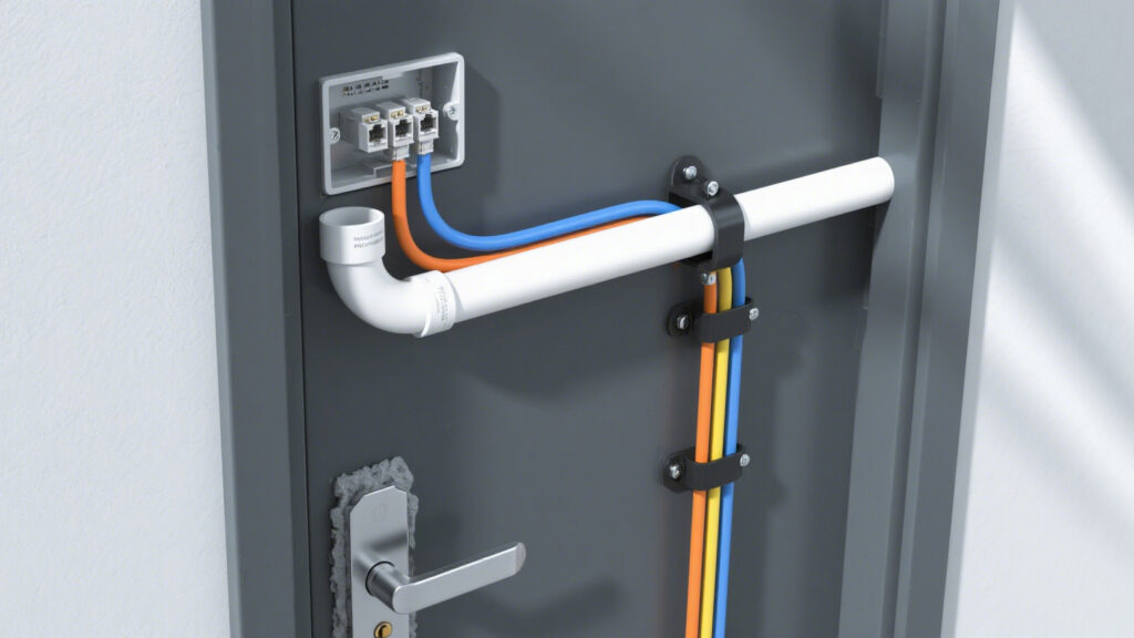
Access control isn’t rocket science. Remember three things: stable power, correct data wiring, and that the relay controls the unlocking timing. The rest is wiring and testing. With patience, you can install it yourself, save on installation costs, and fully understand how your access control system works.
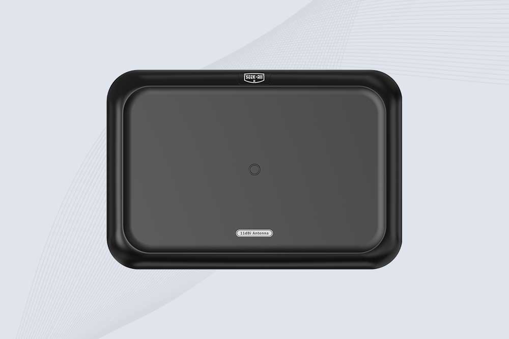
SSD-A11 UHF RFID antenna features 840–960 MHz adjustable frequency, ≥10.5 dBi gain, circular polarization and 50Ω impedance for fixed RFID systems.
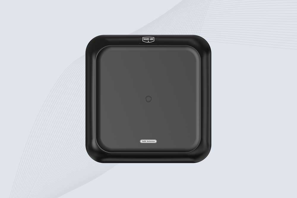
SSD-A09 is a 9 dBi UHF RFID antenna with 840–960 MHz adjustable frequency, circular polarization, 50Ω impedance and directional 60° × 60° coverage.
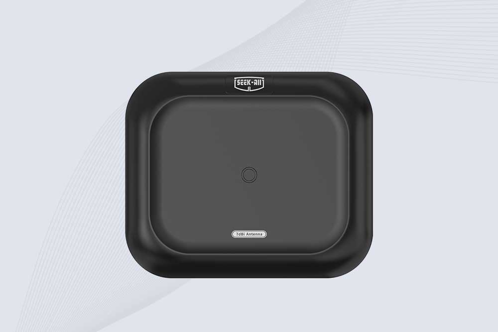
Explore the SSD-A07 UHF RFID antenna with 7 dBi gain, circular polarization, adjustable 840–960 MHz frequency, and 60°/75° beamwidth for stable RFID read/write performance.

SSD-A06 UHF RFID antenna with circular polarization, adjustable 840–960 MHz frequency, ≥4.5 dBi gain, and a compact directional design for RFID systems.

Learn how companies use OEM RFID reader modules to build custom RFID devices for smart cabinets, industrial automation, warehouse systems, and medical equipment tracking.
More
Vehicle RFID tags are essential components for smart vehicle identification, access control, and fleet management. They are widely used in parking lots, logistics parks, toll roads, and smart city systems to enhance management efficiency and secur...
More
Wondering if handheld RFID scanners are worth it for your small business? Explore cost benefits, time savings, and how Cykeo’s solutions maximize ROI.
More
Discover how RFID for tracking improves asset visibility, inventory accuracy, and operational efficiency. Learn proven RFID tracking applications, industry data, and deployment insights from Cykeo experts.
More