Why do businesses prefer USB-powered RFID readers for flexible tracking?
561Discover why USB-powered RFID readers are ideal for flexible asset tracking. Learn about plug-and-play setup, cost efficiency, and multi-location applications.
MoreAll RFID Product
If you’ve ever worked on an RFID project and found your read range mysteriously dropping or the signal acting unstable, there’s a good chance the problem wasn’t the reader or the tag—it was the antenna matching. It’s one of those quiet, behind-the-scenes details that can completely decide whether your RFID system performs like a champ or struggles to read a tag five centimeters away.
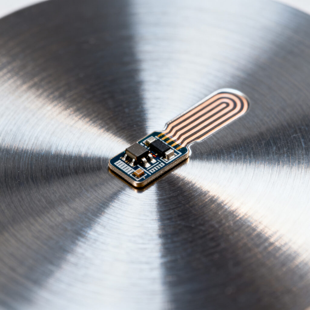
Let’s talk about what antenna matching actually means, why it matters, and how you can get it right without losing days tuning tiny capacitors.
In plain language, antenna matching is about making sure your RFID antenna and chip (or reader module) are on the same page. Every antenna has an impedance—sort of like its “resistance” to an electrical signal—and every RFID IC has its own impedance, too. If those two numbers don’t align, energy bounces back instead of transferring smoothly.
In RFID, that bounce means one thing: wasted power. And wasted power means poor read range, unstable data, and frustrated end users.
For most UHF RFID systems (usually running around 860–960 MHz), you want everything tuned around 50 ohms to make the system happy.
Think of this like tuning a radio or guitar. The frequency’s there, the energy’s there—but if it’s even slightly off, it just doesn’t sound right. Same with RFID signals: when the antenna and chip resonate together, you get strong, clean communication. When they don’t, performance tanks.
So, the real purpose of matching is to make sure the radio waves travel efficiently, with minimal reflection and loss. Most engineers handle this using LC (inductor-capacitor) networks or microstrip adjustments on the PCB.
Here’s how it usually goes in the lab or on the production line:
Step 1 – Pick Your Frequency Band
Decide which band you’re working with — LF, HF, or UHF. Each one behaves differently, especially when it comes to how easily signals bounce or fade.
Step 2 – Measure Impedance
Grab your network analyzer and actually measure the antenna impedance. Don’t rely on simulations alone—they’re great, but reality always throws a curveball.
Step 3 – Simulate Your Matching Network
Use a tool like ADS, CST, or HFSS to model a network that brings your antenna closer to 50 ohms. This is where you decide which components—inductors, capacitors, or transmission lines—fit best.
Step 4 – Build and Test
Assemble the prototype and check your return loss (S11). Ideally, you want it under -10 dB; under -15 dB is even better. Fine-tune your components until you hit that sweet spot.
Step 5 – Validate in the Real World
Here’s where a lot of projects go wrong. Engineers test matching in the lab, but once the tag gets glued to metal or a curved surface, the frequency shifts. Always test the antenna in its actual environment.
For metal or flexible tags, geometry tuning usually gives better results because you don’t have the room for a complex matching network.
If you’ve matched dozens of antennas, you already know how easily things can go sideways.
Here are the usual suspects:
In short, design for tolerance. Leave yourself some margin instead of chasing perfection on paper.
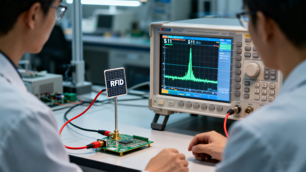
Take a typical UHF metal-tag case. Metal reflects radio waves, so your antenna’s resonance shifts down. The quick fix? Use a patch or folded dipole antenna, then add a small capacitor or shorted stub to pull the impedance back in range.
Before matching, your S11 might be around -5 dB (meaning a lot of energy is bouncing back). After tuning, it can drop to -20 dB or lower, and suddenly your read range doubles. That’s the kind of improvement your client feels immediately.
If you’re supplying or integrating RFID systems, understanding antenna matching is not just a technical skill — it’s a business advantage. You can:
Clients notice when your systems just work out of the box. That reliability starts with a well-matched antenna.
RFID antenna matching may look like a small checkbox in your design list, but it’s the hidden backbone of system performance. Whether you’re building a rugged industrial reader or designing compact tags, the time you spend tuning will always pay off.
It’s a bit like fine-tuning an engine. The average user won’t see what’s under the hood — but they’ll absolutely feel it when it runs smoother, faster, and longer.
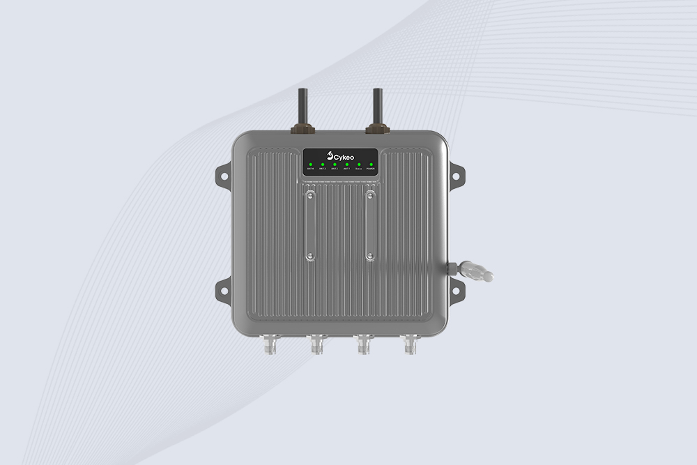
Cykeo CK-C1 industrial Forklift RFID Reader features 20m read range, 600 tags/sec scanning, Impinj R2000 chipset, and IP67 rugged design. Ideal for warehouse logistics and manufacturing. Supports ISO 18000-6C/6B protocols.
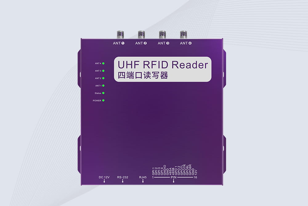
Cykeo CK-R4 industrial UHF RFID Fixed Reader features 4 TNC ports, 400+ tags/sec speed, IP67 housing, and global frequency compliance for vehicle inspection, smart warehouse, and asset management systems.
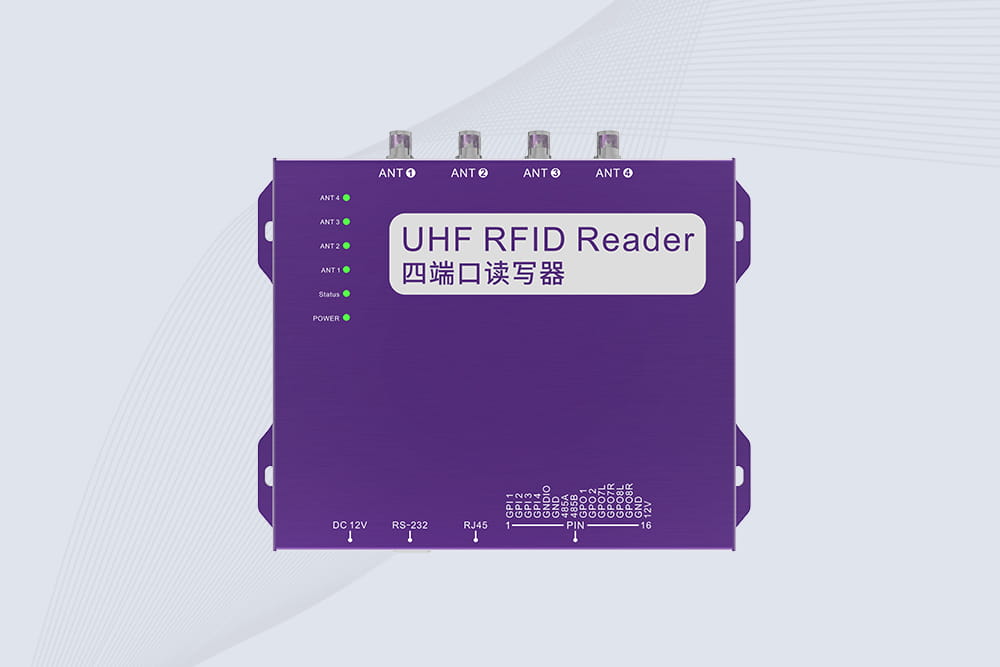
Cykeo’s CK-R4L 4-port Fixed UHF RFID Reader delivers 400 tags/sec scanning, ISO 18000-6C compliance, and IP65 protection. Ideal for warehouse automation, manufacturing WIP tracking, and logistics management.
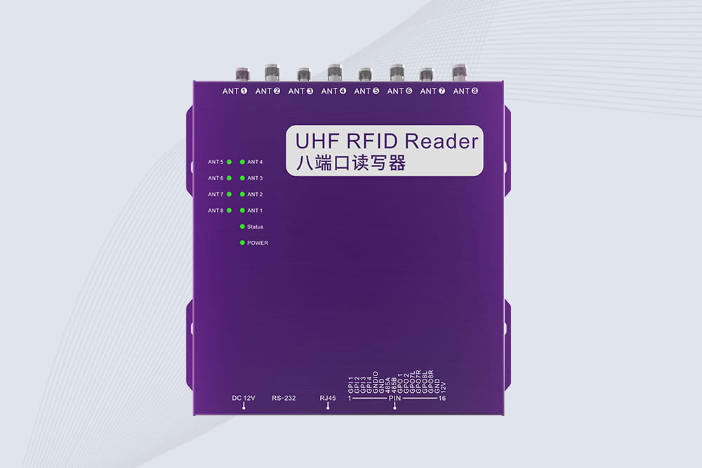
CYKEO CK-R8L Fixed RFID Reader with 8-port UHF design, Impinj-based RF core and up to 20m read range. An industrial Fixed RFID Reader for vehicle inspection, warehouse portals, smart manufacturing lines and secure access checkpoints.
Discover why USB-powered RFID readers are ideal for flexible asset tracking. Learn about plug-and-play setup, cost efficiency, and multi-location applications.
MoreTest RFID tags using your smartphone and when you should switch to a professional RFID reader. This guide covers NFC testing, UHF tag limitations, and tips for efficient RFID tag management in warehouses and logistics.
MoreDiscover how a hospital parking system using RFID improves emergency vehicle access, speeds up gate operations, and organizes staff and visitor parking through touchless automation and smart data tracking.
MoreThe Android RFID Emulator leverages Host-based Card Emulation (HCE) to turn Android phones into RFID/EPC tags. It enables low-cost testing, access control simulation, and rapid prototyping—making it an essential tool for RFID system integrators an...
More