 Cykeo RFID IoT Solution Products R&D Manufacturer
Can I Read RFID Chips with an RF Gun?
288Wondering, "Can I read RFID chips with an RF gun?" CYKEO explains how UHF RFID pistol-grip scanners work for inventory, their read range, and what tags they work with.
MoreAll RFID Product
The question how to make a RFID reader module pops up in maker forums and engineering labs alike. While you can buy a pre-built module for a few dollars, building one from the IC up is a fantastic way to deeply understand the RF (radio-frequency) fundamentals. Let’s be clear: it’s not a single-evening Arduino shield project. It involves careful circuit design, PCB layout, and antenna tuning. Here’s a realistic breakdown of what it takes.
Step 1: The Critical Choice – Picking Your Frequency
You don’t just start soldering. The first and most important decision is frequency: 125 kHz (LF), 13.56 MHz (HF/NFC), or 860-960 MHz (UHF). For a first-time diy rfid reader project, 13.56 MHz is the most accessible. The chips are common, and the antenna is a manageable size. We’ll focus on that. The popular MFRC522 chip from NXP is the go-to for this. Get its 100+ page datasheet—that’s your bible now.
Step 2: Gathering the Core Components & Designing the Circuit
Your RFID module needs more than just the RFID IC. You’ll need:
Step 3: The Build – Soldering and Assembly
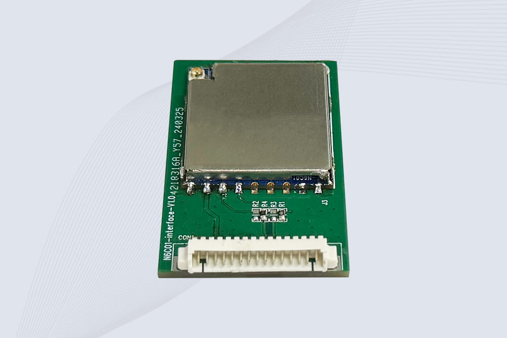
Soldering and assembling the rfid reader board requires a steady hand and fine-pitch soldering skills. The MFRC522 is a QFN package—its pins are underneath. You’ll likely need a hot-air rework station. Use plenty of flux. Solder the crystal and matching network components as close to the chip as physically possible. Any extra wire length here introduces parasitic inductance and kills performance.
Step 4: The Make-or-Break Phase: Antenna Tuning
Once assembled, you must tune the antenna. You’ll need an oscilloscope and a Vector Network Analyzer (VNA) is ideal. You’re checking if the antenna circuit resonates sharply at 13.56 MHz. You adjust the matching capacitor values (often using variable caps during tuning) to get the deepest dip at the right frequency on your scope or VNA. This is not optional. An untuned antenna gives you a read range of millimeters, if it works at all.
Step 5: Programming and Testing
With a hopefully functional hardware, you now write firmware. The chip communicates via SPI or I2C with a microcontroller (like an Arduino). Your code must initialize the chip, manage the anti-collision protocol, and read the tag’s UID. This is where troubleshooting rfid reader communication issues begins. Use a logic analyzer on the SPI bus. Is the chip responding to commands? Is the RFID tags responding? Is the signal clean?
The Hard Truth and a Practical Alternative
Learning how to make a rfid reader module is an excellent educational deep dive into RF principles. However, for any real-world application—access control, inventory—the performance, stability, and regulatory certification (FCC, CE) of a pre-built, professionally engineered module from a vendor like CYKEO are far superior and more cost-effective in the long run. Building one teaches you why those modules are worth every penny.

Wondering, "Can I read RFID chips with an RF gun?" CYKEO explains how UHF RFID pistol-grip scanners work for inventory, their read range, and what tags they work with.
More
Learn how to connect fixed RFID readers to SAP ERP for real-time inventory updates. Explore middleware, API integration, and data mapping best practices.
More
Discover how RFID technology and smart cabinets transform factories and assembly lines. Track parts, tools, and inventory in real-time, prevent mistakes, and optimize production with full visibility.
More
Not all RFID parking tags perform the same. Compare windshield tags, headlight tags, license plate tags, hang tags and active RFID tags by installation, reading distance, lifespan, cost and tamper resistance before selecting your parking access so...
More