RFID vs Bluetooth Beacons: Which One Actually Fits Your Needs?
280Struggling to choose between RFID and Bluetooth beacons? We compare range, cost, accuracy, and real-world use cases to help you decide.
MoreAll RFID Product
RFID antenna design is basically about creating antennas for RFID tags and readers — whether passive, semi-passive, or active. You have to think about frequency, structure, impedance, materials, environment, and a whole list of details. And trust me, it’s not just “draw it in CAD and run a sim.” The reality check comes with manufacturing errors, weird reflections, or a warehouse full of metal shelves killing your read range.
In papers (like “Antenna design for UHF RFID tags: A review …”) you’ll often see the same key elements: calculating read range, taking into account what the tag is stuck on (metal box, liquid container, or just plastic), tolerances in production, and the gap between simulations and real-world testing.

From different sources and my own projects, here are the big theoretical pieces:
From my own hands-on projects:

| Problem | Likely Cause | Fix |
|---|---|---|
| Sim looks great but poor real reads | Ignored metal/liquid effects, wrong material assumptions, bad solder/feed connection | Do mock-ups, test in real environment, use absorber or spacing tricks |
| Matching shifts after production | PCB tolerance, copper thickness, humidity/temperature effects | Account for tolerance, leave tuning options (trim line, add small caps) |
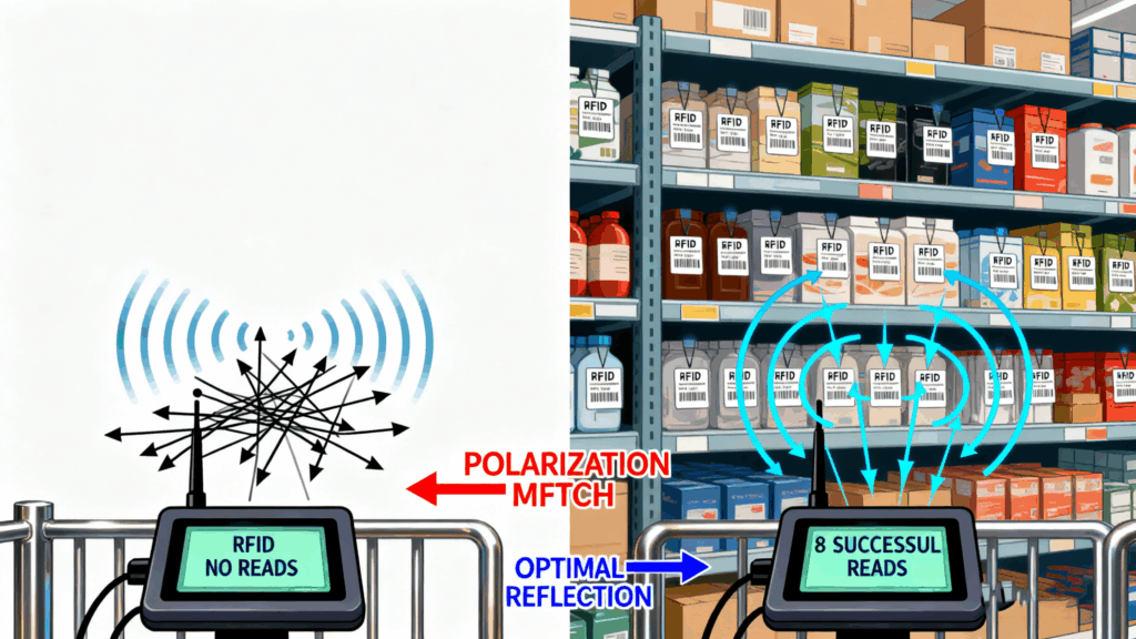
| Tags “disappear” at certain angles | Polarization mismatch | Use circular polarization, test multiple orientations |
| High gain antenna but poor near coverage | Narrow beam misses close/side tags | Balance gain vs beamwidth, use multiple antennas |
RFID antenna design is part theory, part art, and a lot of field hacking. My personal lessons:

Cykeo’s CK-A5 industrial Near Field RFID Antenna enables error-free scanning in dense shelves. Features 5cm-2m adjustable range, IP67 rating, ISO15693/NFC support for pharmaceutical/retail inventory.

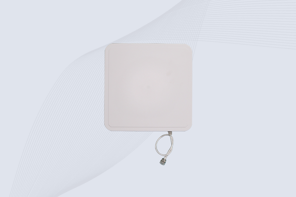
Cykeo’s CK-A12C UHF Large RFID Antenna delivers 12dBi gain, 840-960MHz global frequency, IP65 ruggedness for logistics/warehousing/automotive. 40° beamwidth ensures stable 15m+ tag reads.

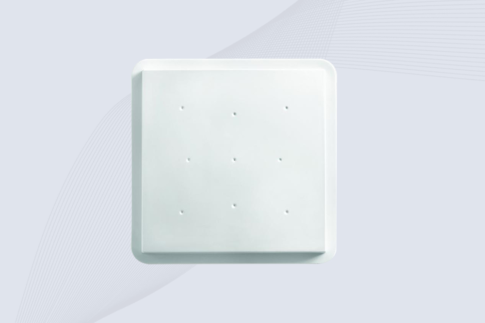
Cykeo CK-A9A industrial UHF RFID reader and antenna kit delivers 10m range, 500 tags/sec, IP65 ruggedness for manufacturing/logistics. Supports EPC Gen2, ISO18000-6C.

Cykeo’s 8dBi UHF RFID antenna and reader kit delivers 10m+ range, 840-960MHz broadband, and IP65 ruggedness for factories, warehouses, and logistics. ISO 18000-6C & EPC Gen2 certified.
Struggling to choose between RFID and Bluetooth beacons? We compare range, cost, accuracy, and real-world use cases to help you decide.
MoreDiscover how RFID tags work, their components, and real-world applications. Learn about passive vs. active tags and Cykeo’s innovative RFID solutions.
MoreLearn how to test RFID tags using your iPhone. Discover Bluetooth reader options, free apps, and troubleshooting tips for quick verification.
MoreDiscover whether handheld RFID readers can scan through metal or liquid containers. Learn about anti-metal tags, UHF limitations, and best practices for reliable detection.
More